
Thread processing insert and processing method thereof

A thread machining and thread cutter technology, applied in the field of thread machining inserts and their machining and machining inserts, can solve problems such as low efficiency and cumbersome tool setting process, and achieve the goal of eliminating tool setting process, preventing mutual interference and eliminating shape and position errors. Effect

Active Publication Date: 2018-11-13
温州天衣精密工具有限公司
View PDF6 Cites 0 Cited by
  • Summary
  • Abstract
  • Description
  • Claims
  • Application Information

AI Technical Summary

Problems solved by technology

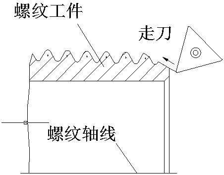
Whether it is the "knife-moving method" or the "knife-relying method", or installing thread cutters and deburring bayonets on the same tool holder, the deburring process cannot be completed in a very simple manner. The tool setting process is cumbersome and inefficient.

Method used


Image

  • Thread processing insert and processing method thereof
  • Thread processing insert and processing method thereof
  • Thread processing insert and processing method thereof

Examples


Embodiment 1

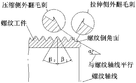
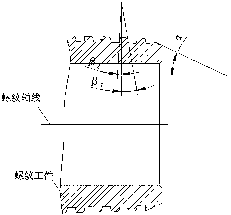
[0029] Such as Figure 5-1 , Figure 5-2 , Figure 6-1 , Figure 6-2 As shown, a thread processing blade includes a blade body 1, the cutting edge side of the blade body is provided with a thread cutting knife 2, and a deburring bayonet 5 is also provided before the thread cutting knife, and the deburring bayonet includes a set The compression side burr cutting edge 3 which is connected to the compression side burr blade and can be used to cut the burrs on the side of the thread tooth profile which bears the tensile load at the front end. Blade 4.

[0030] The angle between the chamfered surface at the beginning of the thread and the thread axis is α, and the angle formed between the side of the tooth profile on the side of the thread tooth that bears the compressive load and the plane perpendicular to the thread axis is β1. The included angle formed between the tooth profile side on the side bearing the tensile load and the perpendicular plane to the thread axis is β2, an...

Embodiment 2

[0040] A kind of thread processing blade comprises a blade body 1, the cutting edge side of the blade body is provided with a thread cutting knife 2, and a deburring bayonet 5 is also provided before the thread cutting knife, and its deburring bayonet includes a front end The compression side burr blade 3 which cuts the burrs on the side of the thread tooth profile bearing the compressive load, and the tension side burr blade 4 which is connected to the compression side burr blade and can be used to cut the burrs on the side of the thread tooth profile which bears the tensile load.

[0041] The angle between the chamfered surface at the beginning of the thread and the thread axis is α, and the angle formed between the side of the tooth profile on the side of the thread tooth that bears the compressive load and the plane perpendicular to the thread axis is β1. The included angle formed between the tooth profile side on the side bearing the tensile load and the perpendicular plan...


PUM

PropertyMeasurementUnit
heightaaaaaaaaaa

Abstract

The invention relates to the field of machines, provides a machining blade, and particularly relates to a thread machining blade and a machining method thereof. The thread machining blade comprises a blade body, a plurality of thread cutting edges which are sequentially arranged and used for turning threads are arranged on the cutting chip side of the blade body, and a burr cutter is arranged on the front sides of the thread cutting edges and comprises a compression side burr cutting edge arranged at the front end and a stretching side burr cutting edge which is connected to the position behind the compression side burr cutting edge and can have the effect of eliminating burrs. The thread machining blade and the machining method have the beneficial effects that the burrs caused by thread turning can be completely avoided through the combination cutter; the outwards-turned and inwards-turned burrs can be turned through the compression side burr cutting edge and the stretching side burr cutting edge connected to the position behind the compression side burr cutting edge; and the reasonable overall structure of the cutter can be achieved through the relation of all included angles, and the problems like mutual interference happening in the cutter machining process are prevented.

Description

technical field [0001] The invention relates to the technical field of machinery, and refers to a processing blade, especially a thread processing blade and a processing method thereof. Background technique [0002] The screw thread is a helical continuous convex part with a specific cross section made on the surface of a cylindrical or conical parent body. The thread is divided into cylindrical thread and conical thread according to the shape of its parent body; it is divided into external thread and internal thread according to its position in the parent body, and it is divided into triangular thread, rectangular thread, trapezoidal thread and zigzag thread according to its cross-sectional shape (tooth shape). And other special shape threads. The existing thread processing is based on the deformation of the cutting processing area and the plasticity of the chips during metal cutting. After the chamfering surface and thread cutting are processed in sequence, burrs will app...

Claims


Application Information

Patent Timeline
Patent Type & Authority Patents(China)
IPC IPC(8): B23G9/00
Inventor 陆耕深王伟民
Owner 温州天衣精密工具有限公司
Learn More