Under-actuated highly-simulated finger integrating coupling and adaptive motion modes

A motion mode and under-actuated technology, which is applied in the direction of manipulators, chucks, manufacturing tools, etc., can solve the problems of poor self-adaptive ability, insufficient grasping force, and low degree of human imitation, so as to achieve strong self-adaptive ability and reduce energy loss , the effect of reducing muscle fatigue

Active Publication Date: 2016-06-08
HARBIN INST OF TECH
View PDF5 Cites 15 Cited by
  • Summary
  • Abstract
  • Description
  • Claims
  • Application Information

AI Technical Summary

Problems solved by technology

[0003] The purpose of the present invention is to provide an underactuated high artificial finger with both coupling and adaptive motion modes, so as to solve the problems of low human imitation degree, poor adaptive ability and insufficient grasping force of the underactuated artificial finger

Method used


Image

  • Under-actuated highly-simulated finger integrating coupling and adaptive motion modes
  • Under-actuated highly-simulated finger integrating coupling and adaptive motion modes
  • Under-actuated highly-simulated finger integrating coupling and adaptive motion modes

Examples


specific Embodiment approach 1

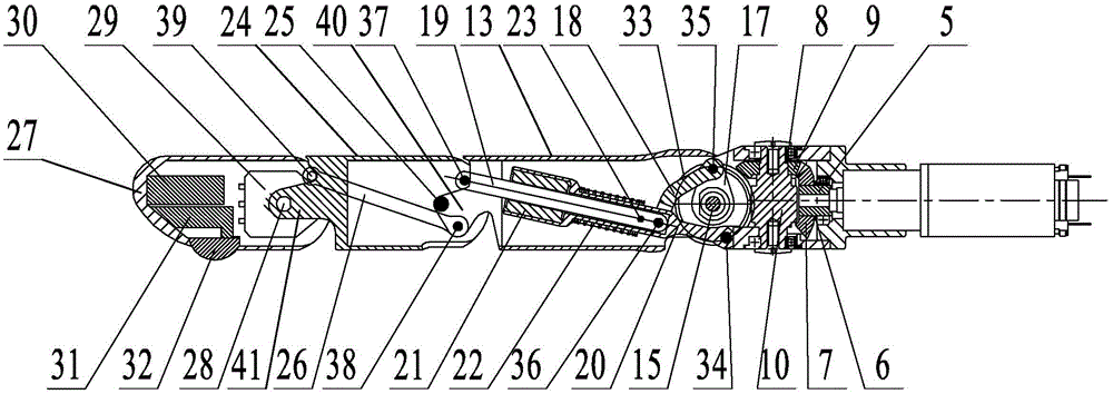
[0021] Specific implementation mode one: combine figure 1 , figure 2 , image 3 , Figure 4 , Figure 5 and Figure 6 Describe this embodiment, this embodiment includes base joint, near phalanx, middle phalanx and far phalanx;

[0022] The base joint includes a base 1, a gear box mount 2, a gear box 3, a motor 4, a bevel gear coupling 5, a first bevel gear 7, a second bevel gear 9 and a worm 10, and the gear box 3 passes through the gear box The mounting seat 2 is fixedly installed on the base 1, and the output shaft of the motor 4 passes through the reduction box 3 and the bevel gear coupling 5 to be connected with the first bevel gear 7 in turn, and the second bevel gear 9 is fixedly installed on the worm 10 and its Mesh with the first bevel gear 7;

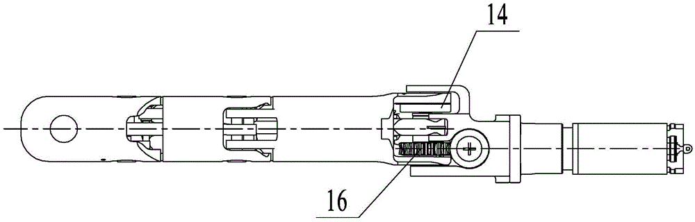
[0023] The proximal knuckle includes a first knuckle housing 13, an MCP shaft 15, a turbine 16, a drive rod connection seat 17, a drive rod 18, a slide rod 19, a slide rod base 20 and a linear bearing 21, the first knuck...

specific Embodiment approach 2

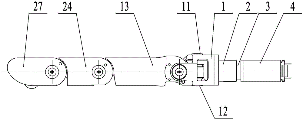
[0030] Specific implementation mode two: combination figure 1 Describe this embodiment, in this embodiment, one end of the first knuckle shell 13 in contact with the second knuckle shell 24 is processed with a first connecting protrusion 40, and the first connecting protrusion 40 is arranged on the second knuckle shell 24. In the knuckle shell 24, the first knuckle shell 13 is connected with the second knuckle shell 24 through the first connecting protrusion 40; the end of the second knuckle shell 24 in contact with the third knuckle shell 27 is processed There is a second connection protrusion 41 , and the second knuckle shell 24 is connected with the third knuckle shell 27 through the second connection protrusion 41 .

[0031] In this embodiment, the setting of the first connection protrusion 40 and the second connection protrusion 41 is to ensure that the connection relationship between the first knuckle shell 13, the second knuckle shell 24 and the third knuckle shell 27 i...

specific Embodiment approach 3

[0032] Specific implementation mode three: combination figure 1 Describe this embodiment. In this embodiment, the base joint also includes an input-end bevel gear adjustment washer 6 and an output-end bevel gear adjustment washer 8. The input-end bevel gear adjustment washer 6 is set on the bevel gear coupling 5, the bevel gear adjustment gasket 8 at the output end is set on the worm 10.

[0033]In this embodiment, the setting of the bevel gear adjustment pad 6 at the input end and the bevel gear adjustment pad 8 at the output end is used to adjust the degree of engagement between the first bevel gear 7 and the second bevel gear 9, and the bevel gear adjustment pad at the output end The sheet 8 is composed of a disc type elastic element, which can adjust the position of the meshing point between the worm 10 and the worm 16 and eliminate the ulnar gap between the worm 16 and the worm 10 . Other unmentioned structures and connections are the same as those in the first or second...


PUM


Abstract

The invention discloses an under-actuated highly-simulated finger integrating coupling and adaptive motion modes, and relates to an under-actuated highly-simulated finger. The existing under-actuated artificial finger is low in humanoid degree, poor in adaptive capability and insufficient in grasping force. The under-actuated highly-simulated finger comprises a base joint, a near finger knuckle, a middle finger knuckle and a far finger knuckle; a reducer casing is fixedly mounted on a base through a reducer casing mounting seat; the output shaft of a motor sequentailly penerates through the reducer casing and a bevel gear coupling and is connected with a first bevel gear; a second bevel gear is fixedly mounted on a worm and is meshed with the first bevel gear; a turbine sleeves an MCP shaft; the worm is meshed with the turbine; a third finger knuckle casing is connected with a second finger knuckle casing through a DIP shaft; the far finger knuckle sleeves the DIP shaft through a position sensor; a finger tip circuit board and a touch sensor circuit board are sequentially fixedly mounted in the third finger knuckle casing; touch sensor circuit colloid penetrates through the bottom of the third finger knuckle casing. The under-actuated highly-simulated finger is applied to intelligent robots.

Description

technical field [0001] The invention relates to an underactuated high-simulation finger, which belongs to the technical field of electromechanical integration. Background technique [0002] The hand is the most complex and delicate tool for human survival and labor. Human beings can use their hands to contact the external environment and obtain information from the environment to better operate the environment. As an important content and component of rehabilitation medical engineering, prosthetic hand is an important means to make disabled people recover and return to society. Therefore, how to design the shape and function to highly imitate the human hand and have a high degree of adaptability to the manipulated object has always been the focus of the field of prosthetic hand research. The development of artificial hands will eventually be user-oriented, therefore, the commercialization of artificial hands is its development trend. Most of the relatively mature commercia...

Claims


Application Information

Patent Timeline
Patent Type & Authority Applications(China)
IPC IPC(8): B25J15/02
CPCB25J15/0009B25J15/0206B25J15/0213
Inventor 姜力程明樊绍巍刘源曾博张玉山杨斌杨大鹏刘宏
Owner HARBIN INST OF TECH
Why Eureka
Try Eureka