Electric vehicle and operation control method thereof

A technology of operation control and electric vehicles, which is applied to motor vehicles, bicycles, two-wheeled bicycles, etc., can solve the problem of high cost and achieve the effect of reducing volume and being easy to carry

Active Publication Date: 2016-06-08
CHANGZHOU AIRWHEEL INTELLIGENT TECH
View PDF9 Cites 19 Cited by
  • Summary
  • Abstract
  • Description
  • Claims
  • Application Information

AI Technical Summary

Problems solved by technology

That is to say, the acceleration and deceleration of the vehicle are inseparable from the joint action of the gyroscope and the accelerometer, and the cost of this control system is generally high

Method used


Image

  • Electric vehicle and operation control method thereof
  • Electric vehicle and operation control method thereof
  • Electric vehicle and operation control method thereof

Examples


Embodiment 1

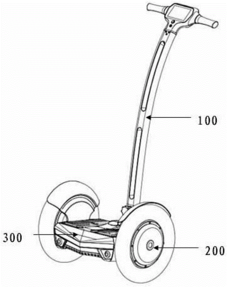
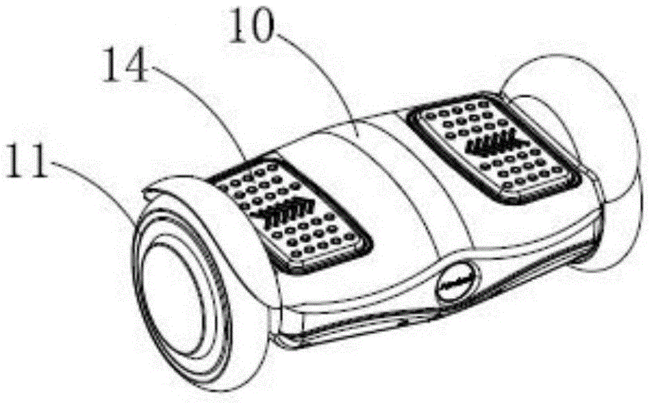
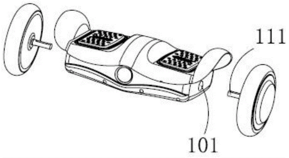
[0029] see figure 2 , image 3 as well as Figure 4 As shown, the electric vehicle of the present invention includes a cabin body 10 and two wheels 11 located on both sides of the cabin body; the inside of the cabin body 10 is provided with a control system and a power supply for providing energy to the wheels. The cabin body is provided with a shaft passing hole 101, and the wheel shaft 111 of the wheel 11 passes through the shaft passing hole 101 and is fixedly arranged inside the cabin body 10, and the cabin body 10 is fixedly arranged relative to the wheel shaft 111. To keep the cabin body 10 stable relative to the axle 111 . The electric vehicle also includes a first pedal 12 and a second pedal 13 for the user's feet to step on, that is, when the user stands on the electric vehicle, his feet step on the first pedal 12 and the second pedal 13 respectively. On the second pedal 13. The first pedal 12 is installed on the cabin body through the first rotating shaft arrang...

Embodiment 2

[0043] The difference from Embodiment 1 is that only one extension part 121 is provided, and in order to make the first pedal 12 have better stability, the extension part 121 is arranged at the middle position of the first pedal 12, and It is located below the first pedal 12 and integrally formed with the first pedal 12 . The first rotating shaft 15 is fixedly provided with a first anti-escape member 151, and the first anti-escape member 151 is close to one end of the first rotating shaft 15, and the first rotating shaft 15 is far away from the first anti-escape member 151 After passing through the first through hole 1211 of the extension part 121 and the second through hole 1611 of the protrusion 161 successively, or passing through the second through hole 1611 of the protrusion 161 and the extension After the first through hole 1211 of the part 121, the second anti-escape member 152 is installed on the end of the first rotating shaft 15 away from the first anti-escape member...

Embodiment 3

[0045] The difference between this embodiment and the first embodiment is that the first connection seat 16 is no longer provided, and the protrusion 161 is directly arranged on the bottom surface inside the cabin body 10 or on the side wall inside the cabin body for accommodating the The hollow groove 162 at the other end of the cylindrical rubber member 20 is also directly arranged on the bottom surface inside the cabin body 10, and other settings are the same as in the first embodiment. In this way, there is no need to set up the first connecting seat 16, which simplifies the structure and saves the cost.


PUM


Abstract

The invention discloses an electric vehicle. The electric vehicle comprises a cabin, two vehicle wheels, a first pedal, a second pedal, a first sensor, a second sensor, a control system and a power source, wherein the two vehicle wheels are installed to the two sides of the cabin through axles; the first pedal and the second pedal can rotate relative to be cabin; the first sensor is used for detecting rotation information of the first pedal; the second sensor is used for detecting rotation information of the second pedal; the control system is connected with the first sensor and the second sensor and is used for controlling the two vehicle wheels to accelerate or decelerate correspondingly; the power source is installed in the cabin; and the cabin is fixedly arranged relative to the axles. By means of the electric vehicle, both hands of a user are freed during electric vehicle control, and the electric vehicle is convenient to carry at ordinary times.

Description

technical field [0001] The invention relates to a walking-replacing tool, in particular to an electric vehicle and its operation control method. Background technique [0002] With the development of the economy, many social problems such as energy shortage, increasingly serious automobile emission pollution, and common traffic jams in cities are becoming increasingly apparent. In recent years, electric vehicles, as a new generation of convenient means of transportation, have become more and more popular among consumers. As an emerging means of transportation, the electric balance car has won the favor of consumers. The patent document No. 201420526748.0 discloses an electric balance car, such as figure 1 As shown, the electric balance vehicle includes a base 300 , a control system disposed inside the base 300 , and wheels 200 disposed on both sides of the base 300 , and the base 300 is also provided with pedals for stepping on. In order to control the turning of the veh...

Claims


Application Information

Patent Timeline
Patent Type & Authority Applications(China)
IPC IPC(8): B62K3/00
Inventor 不公告发明人
Owner CHANGZHOU AIRWHEEL INTELLIGENT TECH
Why Eureka
Try Eureka