Friction conveying system

A conveying system and friction-driven technology, which is applied in conveyors, mechanical conveyors, transportation and packaging, etc., can solve the problems of short-term no drive for conveying loads, high machining accuracy of mechanical parts, and high precision requirements for equipment installation and debugging, etc., to achieve performance Reliable, low-cost, high-speed transportation, and the effect of increasing production costs

Active Publication Date: 2016-06-08
GUANGZHOU MINO AUTOMOTIVE EQUIP CO LTD
View PDF6 Cites 8 Cited by
  • Summary
  • Abstract
  • Description
  • Claims
  • Application Information

AI Technical Summary

Problems solved by technology

However, the above driving and guiding methods have high requirements on the machining accuracy of mechanical parts, equipment installation and debugging accuracy, and the current friction conveying system has the phenomenon that the conveying load is temporarily not driven between stations.

Method used


Image

  • Friction conveying system
  • Friction conveying system
  • Friction conveying system

Examples


Embodiment Construction

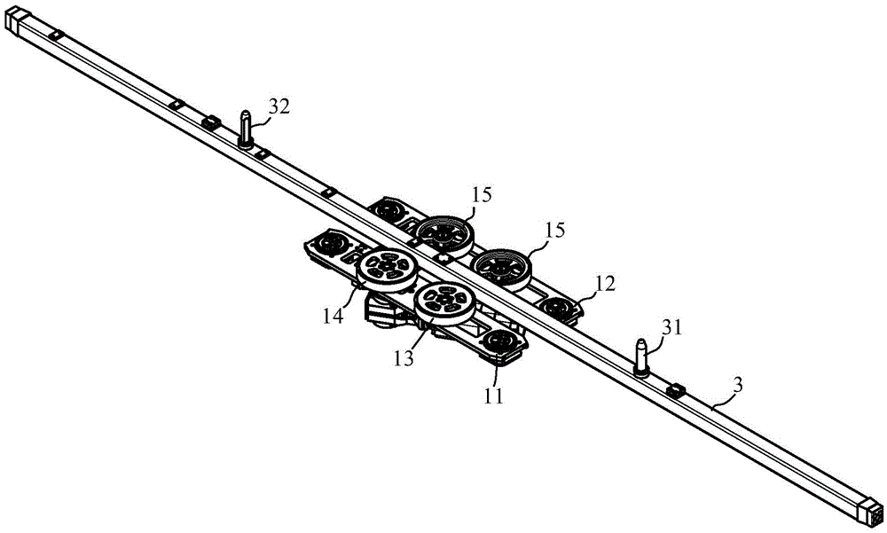
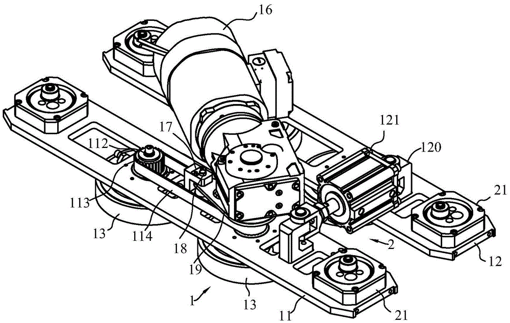
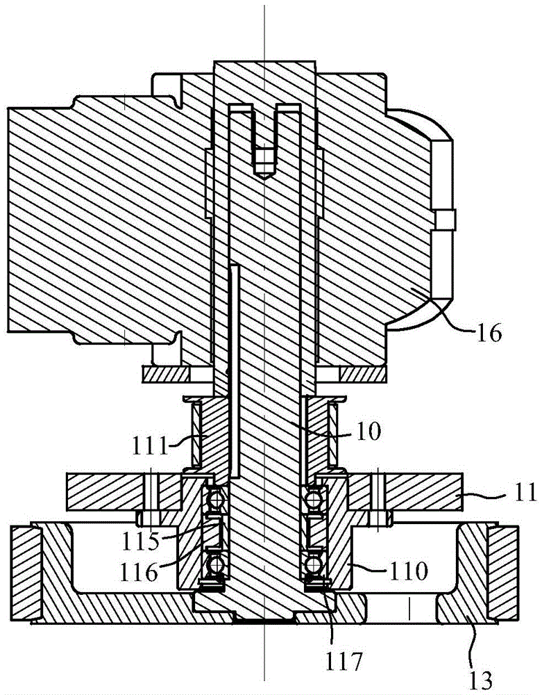
[0021] refer to Figure 1 to Figure 5 , which shows the specific structure of the preferred embodiment of the present invention. The structural features of each element of the present invention will be described in detail below, and if there is a description of the direction (up, down, left, right, front and back), it is based on figure 1 The shown structure is a reference description, but the actual use direction of the present invention is not limited thereto.

[0022] The present invention provides a friction conveying system, comprising a friction drive unit 1, a clamping unit 2 and a friction drive component. The friction drive unit 1 comprises a rotation drive component, a first connecting rod 11, a second connecting rod 12, and The first roller on the first connecting rod 11 and the second roller on the second connecting rod 12, the clamping unit 2 includes a roller that can drive the first connecting rod 11 and the second connecting rod 12 close together so that the ...


PUM


Abstract

The invention discloses a friction conveying system. The friction conveying system comprises a friction drive unit, a clamping unit and a friction drive part. The friction drive unit comprises a rotation drive part, a first connecting rod, a second connecting rod, a first wheel arranged on the first connecting rod and a second wheel arranged on the second connecting rod. The clamping unit comprises a clamping drive part capable of driving the first connecting rod and the second connecting rod to get close to each other so as to enable the outer circle face of the first wheel and the outer circle face of the second wheel to clamp the friction drive part. The rotation drive part can drive the first wheel and/or the second wheel to rotate and enables the friction drive part clamped between the first wheel and the second wheel to move through friction force. By means of the wheels, the friction drive part is driven at a high speed through friction, so that the low-cost and high-speed transportation is achieved, the cost is reduced, performance is reliable, installing is convenient, and the conveying requirement of an industrial automatic production line is met.

Description

technical field [0001] The invention is used in the technical field of industrial automation equipment, and in particular relates to a friction conveying system. Background technique [0002] With economic globalization and high production efficiency, global manufacturing is bound to be intelligentized. At the same time, people's living standards are improving and labor costs are increasing. It is bound to be particularly important to develop fully automatic industrial manufacturing. The automatic conveying system is the main artery of the entire industrial production line, and it is a conveying machine that transmits at high speed within a certain distance. At present, for the long-distance transportation of loads, rack and pinion drives, belt conveyors, linear guide rail sliders and roller guides are often used. However, the above driving and guiding methods have high requirements on the machining accuracy of mechanical parts, equipment installation and debugging accuracy...

Claims


Application Information

Patent Timeline
Patent Type & Authority Applications(China)
IPC IPC(8): B65G35/00
CPCB65G35/00B65G21/10B65G35/06B65G13/12B65G13/06B65G25/065B65G2812/12
Inventor 李军辉杨猛张洪臣陈振城李庆
Owner GUANGZHOU MINO AUTOMOTIVE EQUIP CO LTD
Why Eureka
Try Eureka