Mechanical part machining guiding device

A technology of guiding devices and mechanical parts, which is applied in the field of mechanical parts processing, can solve the problems of low efficiency of mechanical parts, and achieve the effects of cost saving, strong practicability, and accelerated processing efficiency

Inactive Publication Date: 2018-03-13
HENAN COLLEGE OF IND & INFORMATION TECH +1
View PDF9 Cites 5 Cited by
  • Summary
  • Abstract
  • Description
  • Claims
  • Application Information

AI Technical Summary

Problems solved by technology

[0004] The invention proposes a mechanical parts processing guiding device, which is to solve the problems that the existing mechanical parts cannot be mechanically guided and the efficiency of manually placing the mechanical parts on the conveyor belt is low. Processing guide

Method used


Image

  • Mechanical part machining guiding device
  • Mechanical part machining guiding device
  • Mechanical part machining guiding device

Examples


Embodiment

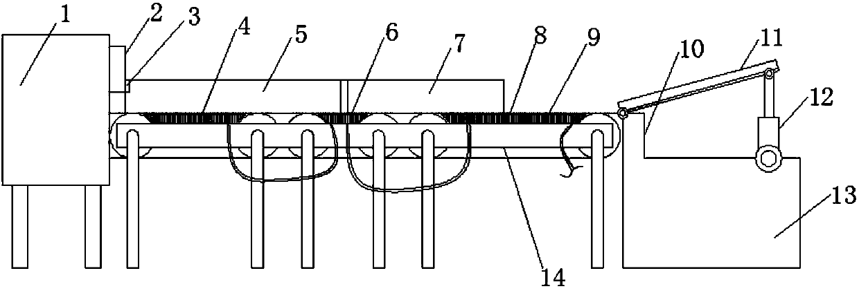
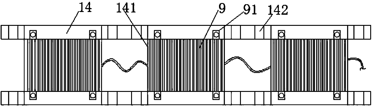
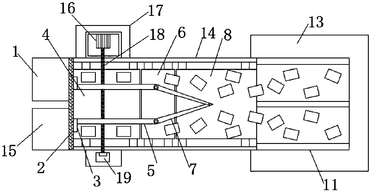
[0029] Embodiment: When the present invention is in use, the mechanical parts are placed randomly on the two feeding plates in the feeding slide 11 manually, and the cylinder 12 can adjust the angle of the feeding slide 11, thereby adjusting the feeding speed, and then The mechanical parts slide down from the feeding plate 11 to the first guide conveyor belt 8, and the two second guide plates 7 divide the conveying path into two. When the mechanical parts pass through the second material guide plate 7, the mechanical parts follow two symmetrical paths Conveying, when the mechanical parts are being conveyed, since the winding 9 is energized, the winding 9 and the metal mounting plate 141 form a magnetic field, so that the metal mechanical parts on the surface of the conveyor belt are adsorbed downward, so that the friction between the mechanical parts and the surface of the conveyor belt Greatly increased, even smoother mechanical parts or smaller parts can be transported using ...


PUM


Abstract

The invention belongs to the field of injection molding machines and particularly relates to a mechanical part machining guiding device. The mechanical part machining guiding device is used for solving the problem that existing mechanical parts which have smooth surfaces and are small in size are difficult to guide and convey. The following scheme is put forwards at present; the mechanical part machining guiding device comprises a conveying rack and a second installation table located on one side of the conveying rack; a first guiding conveying belt, a second guiding conveying belt and a feeding conveying belt are sequentially arranged on the conveying rack; second installation tables which are symmetrically arranged are arranged on the two sides of the conveying rack; and the top end of one of the second installation tables is provided with a driving motor. By means of the mechanical part machining guiding device, mechanical guiding conveying can be achieved in the mechanical part machining process, parts are not likely to slide on the a conveying belt in the conveying process, metal mechanical parts which have different surface smooth degrees or are small in size can be guided and transported, selection space is increased, in addition, the machining efficiency is greatly increased, guiding conveying can be conducted on different specifications of parts, and practicability ishigh.

Description

technical field [0001] The invention relates to the technical field of machining of mechanical parts, in particular to a guiding device for machining of mechanical parts. Background technique [0002] The basic elements that make up a machine are called mechanical parts. A machine element, also known as a machine part, is an inseparable single piece that makes up a machine and a machine. It is the basic unit of a machine. Since the emergence of machinery, there have been corresponding mechanical parts. But as a discipline, mechanical parts are separated from mechanical construction and mechanics. With the development of the machinery industry, the emergence of new design theories and methods, new materials, and new processes, mechanical parts have entered a new stage of development. Theories such as finite element method, fracture mechanics, elastohydrodynamic lubrication, optimization design, reliability design, computer-aided design (CAD), solid modeling (Pro, Ug, Solidw...

Claims


Application Information

Patent Timeline
Patent Type & Authority Applications(China)
IPC IPC(8): B65G47/14B65G47/30B65G15/58
Inventor 李涛涛
Owner HENAN COLLEGE OF IND & INFORMATION TECH
Why Eureka
Try Eureka