Feed conveying device with side leakage prevention function

A conveying device and anti-side leakage technology, applied in the field of feed conveying devices with anti-side leakage function, can solve problems such as blockage, side leakage of feed, accumulation of feed conveying, etc., improve conveying speed and smoothness, and prevent feed leakage detection , The effect of preventing side leakage of feed

Active Publication Date: 2022-04-05
XINXIANG ZHENGYUAN MACHINERY EQUIP
View PDF7 Cites 2 Cited by
  • Summary
  • Abstract
  • Description
  • Claims
  • Application Information

AI Technical Summary

Problems solved by technology

[0004] In order to overcome the shortcomings of the existing feed conveying equipment that lead to the accumulation and blockage of feed conveying, and the side leakage of feed, and the side leakage of feed under the action of air flow, the present invention provides a feed conveying device with the function of preventing side leakage. device

Method used


Image

  • Feed conveying device with side leakage prevention function
  • Feed conveying device with side leakage prevention function
  • Feed conveying device with side leakage prevention function

Examples


Embodiment 1

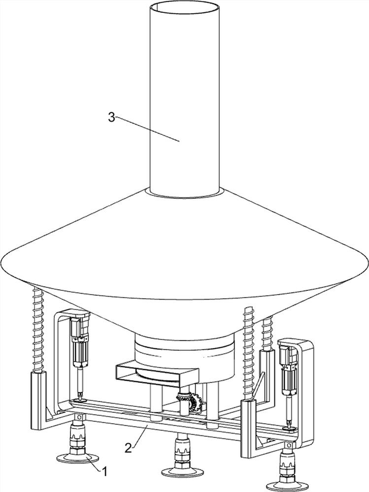
[0032] A feed conveying device with anti-side leakage function, such as Figure 1-Figure 9 As shown, it includes a fixed foot 1, a U-shaped fixed frame 2, a feeding pipe 3, a gravity switch system, an anti-blocking system and a return system; there are three fixed feet 1; the upper surface of the three fixed feet 1 is fixed. U-shaped fixed frame 2 is connected; gravity switch system is installed on U-shaped fixed frame 2; anti-blocking system is installed on the lower side of gravity switch system; anti-blocking system is connected with U-shaped fixed frame 2; return system is installed on the upper side of gravity switch system ; The return system is connected with a feeding pipe 3, and the lower part of the feeding pipe 3 is set as a telescopic structure.

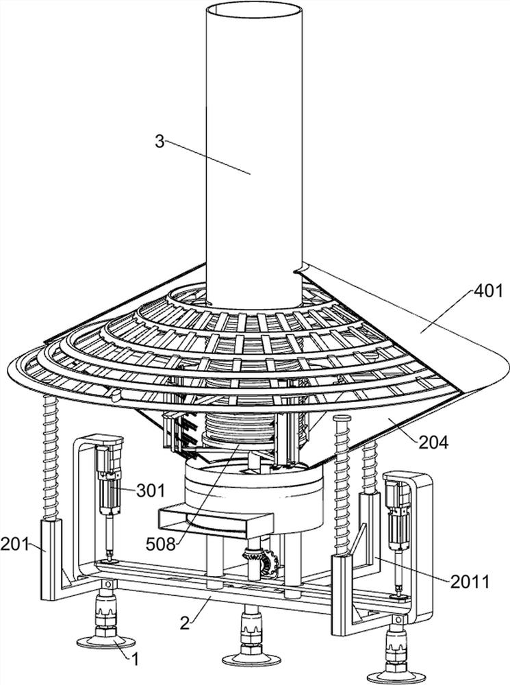
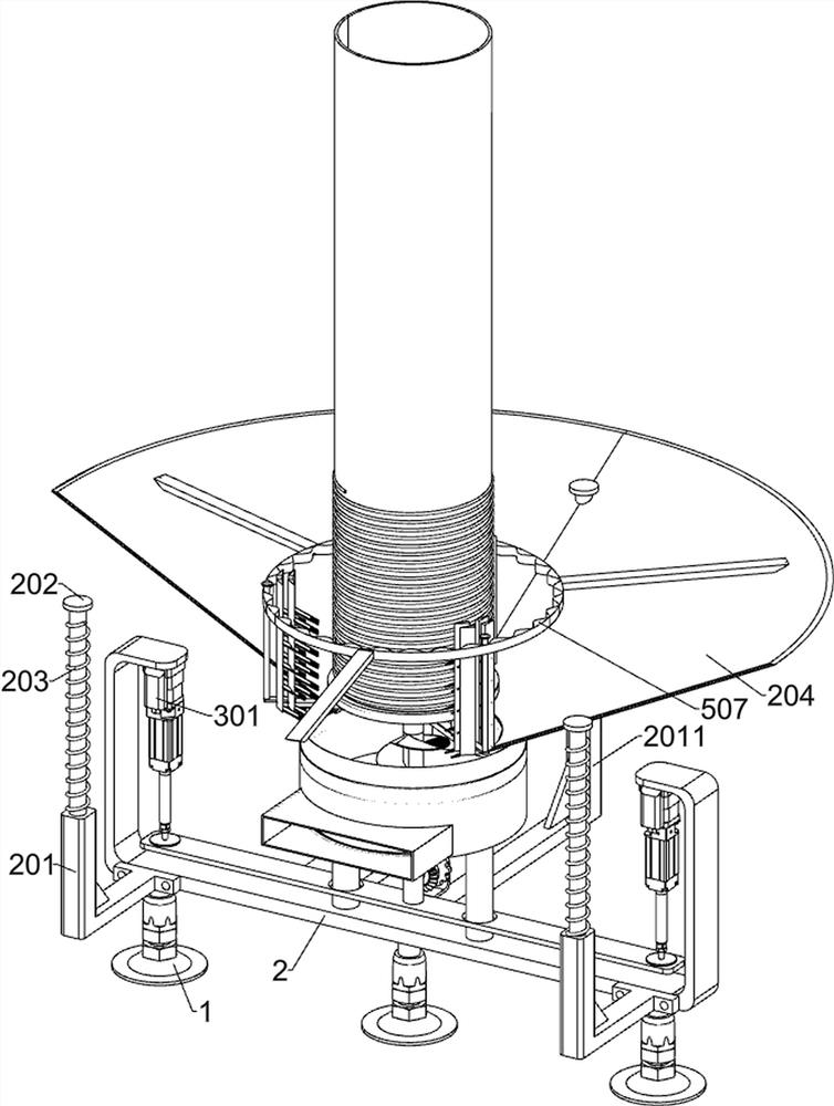
[0033]The gravity switch system includes a first L-shaped plate 201, a round rod 202, a first elastic member 203, a funnel 204, a first connecting rod 205, a hollow limit rod 206, a first shifting block 207, a second shif...

Embodiment 2

[0044] On the basis of Example 1, such as figure 1 and Figure 10-Figure 12 As shown, an auxiliary dredging system is also included. An auxiliary dredging system is installed on the upper side of the dredger 306. The auxiliary dredging system includes a second elastic member 501, a connecting column 502, a first separating plate 503, a second separating plate 504, and a pushing plate. 505, the third connecting plate 506, the shaking ring 507, the connecting ring 508 and the sliding rod 509; the upper side of the dredge 306 is fixedly connected with three second elastic members 501 arranged in an annular array; the telescopic ends of the three second elastic members 501 are connected by Each block is fixed with a connecting column 502; the telescopic ends of the three second elastic members 501 are respectively fixed with two first separation plates 503 and two second separation plates 504; the six first separation plates 503 are located in the six The outer sides of the two s...


PUM


Abstract

The invention relates to the field of feed conveying, in particular to a feed conveying device with a side leakage prevention function. The invention relates to a feed conveying device, and aims to solve the problems that accumulation and blockage of feed conveying are caused by existing feed conveying equipment, side leakage of the feed is caused, and side leakage of the feed is further caused under the action of airflow. According to the technical scheme, the feed conveying device with the side leakage prevention function comprises fixing bottom feet, a U-shaped fixing frame and the like; the number of the fixing bottom feet is three. A U-shaped fixing frame is fixedly connected to the upper surfaces of the three fixing bottom feet. When powdery feed is conveyed, in order to fundamentally solve the problem of side leakage of the feed, namely, the problems of feed blockage and diffusion and side leakage formed under the action of airflow, the feed accumulated in the funnel is automatically dredged, so that the feed cannot be blocked, the conveying speed of the feed is increased, and the conveying efficiency of the feed is improved. Meanwhile, the backflow grid plate is used for guiding and guiding the airflow, so that the airflow forms backflow.

Description

technical field [0001] The invention relates to the field of feed delivery, in particular to a feed delivery device with side leakage prevention function. Background technique [0002] With the gradual development of animal husbandry, the production of feed has also been greatly improved. During the production process, feed needs to go through multiple processes. Therefore, it needs to go through long conveying equipment to transport the feed to a specific location. In the existing Technology When conveying powdered feed, due to technical limitations, the powdered feed will form accumulations at the outlet during the conveying process, which will cause the outlet of the feed to be blocked, making the feeding rate of the feed far slower than that of the feeder. Feed rate, with the accumulation of feed, the feed will leak sideways. During the transportation process, pipelines are generally used for transportation. Therefore, a certain airflow will be formed at the outlet of th...

Claims


Application Information

Patent Timeline
Patent Type & Authority Applications(China)
IPC IPC(8): B65G69/18B65D88/70B65D88/64
CPCY02A40/81
Inventor 郭文娟关婷婷聂红敏刘娜段凤娟管升诚马园园刘小提曹婧魏源张贺敏徐琪胡玉灵周雪梅
Owner XINXIANG ZHENGYUAN MACHINERY EQUIP
Why Eureka
Try Eureka