Part discharging device

A technology of unloading and unloading, which is applied in the field of unloading equipment, can solve the problems of reducing the market competitiveness of enterprises, reducing profits, and reducing the efficiency of operators to take materials, so as to shorten the time required for taking materials and solve the problem of production efficiency decline , The effect of improving the efficiency of material extraction

Inactive Publication Date: 2016-06-08
四川逢顺商贸有限公司
View PDF0 Cites 0 Cited by
  • Summary
  • Abstract
  • Description
  • Claims
  • Application Information

AI Technical Summary

Problems solved by technology

[0002] When spraying pipe fittings, pipe fittings need to be conveyed. The existing conveying equipment only has a single conveying function, which uses manual loading and unloading, which is inconvenient to operate, requires a lot of manpower due to high labor intensity, and has a low degree of automation, which cannot meet modern requirements. The need for paint delivery
At present, the known work of taking out materials from the material tray is done manually by operators. The efficiency of manual material removal is relatively low, which cannot keep up with the efficient production of the production line, or requires multiple operators to manually remove materials to meet the high-efficiency production line. In this way, the consumption of human resources on each production line will increase, and the production cost of products will increase, reducing the profit of the enterprise and reducing the market competitiveness of the enterprise.
When the production line runs efficiently for a long time, the employees who take the materials do repetitive actions at high speed for a long time, and are prone to fatigue, which reduces production efficiency and induces related safety hazards
After the operator finishes taking the materials manually, he has to collect the empty plates containing the materials together, which increases the operating procedures and labor intensity of the operators, reduces the efficiency of the operators to take materials, and affects the production efficiency of the enterprise

Method used


Image

  • Part discharging device
  • Part discharging device
  • Part discharging device

Examples


Embodiment

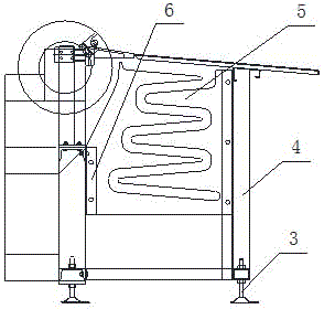
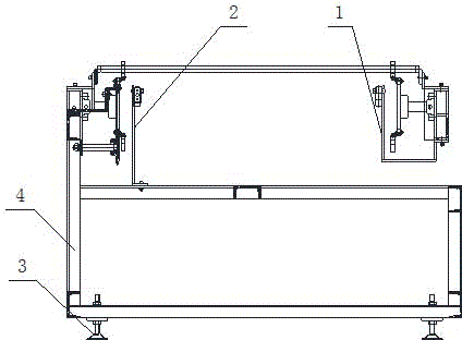
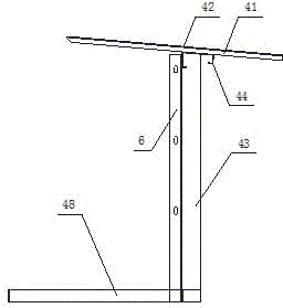
[0021] Example: see figure 1 , figure 2 , image 3 , Figure 4 , Figure 5 and Figure 6 , a lowering device, including a tripod 4 and several legs arranged at the bottom thereof, the legs are adjustable feet 3 that can adjust the height, and the tripod 4 is also provided with a blanking mechanism I1 and a blanking mechanism II2, A defective product storage plate 5 is provided between the blanking mechanism I1 and the blanking mechanism II2, and the parts are connected by detachable components; the tripod 4 includes a vertically arranged column 43, and the column 43 is arranged on the On the lower cross brace 48 at the lowermost end, the side plates of the column 43 are arranged side by side to connect the angle steel 6, and the upper beam 44 is arranged at the upper end of the column 43, and the upper beam 44 is connected to the upper guide bar 41, and the surface of the upper guide bar 41 is provided with a soft silicone skin 42. The middle part of 43 is connected wit...


PUM


Abstract

The invention provides a part discharging device which comprises a foot stand and a plurality of supporting feet arranged at the bottom of the foot stand. The supporting feet are adjusting feet capable of adjusting the height of the device. The foot stand is further provided with a discharging mechanism I and a discharging mechanism II, an unqualified product storage plate is arranged between the discharging mechanism I and the discharging mechanism II, and all the components are connected through detachable assemblies. The foot stand comprises vertically arranged stand columns which are arranged on lower horizontal supports located at the lowermost end. Connecting angles are arranged on a side plate of each stand column side by side, an upper cross beam is arranged at the upper end of each stand column, the upper portion of each upper cross beam is connected with an upper guide bar, and soft silica gel sheets are attached to the surfaces of the upper guide bars. Transversely arranged lower supports are connected to the middle of each stand column, and a connecting plate is arranged at the end, away from the corresponding stand column, of each lower support; all the parts are fixed into a unified whole through welding. By means of the part discharging device, material taking time can be shortened, the efficient production requirement is met, production efficiency is effectively improved, and production cost of products is lowered; the manpower resource is saved, and product producing cost is lowered.

Description

technical field [0001] The invention relates to the field of unloading equipment, in particular to a unloading device. Background technique [0002] When spraying pipe fittings, pipe fittings need to be conveyed. The existing conveying equipment only has a single conveying function, which uses manual loading and unloading, which is inconvenient to operate, requires a lot of manpower due to high labor intensity, and has a low degree of automation, which cannot meet modern requirements. The need for paint delivery. At present, the known work of taking out materials from the material tray is done manually by operators. The efficiency of manual material removal is relatively low, which cannot keep up with the efficient production of the production line, or requires multiple operators to manually remove materials to meet the high-efficiency production line. In this way, the consumption of human resources on each production line will increase, and the production cost of products ...

Claims


Application Information

Patent Timeline
Patent Type & Authority Applications(China)
IPC IPC(8): B65G47/74
Inventor 徐顺献
Owner 四川逢顺商贸有限公司
Why Eureka
Try Eureka