Three-dimensional knitted side boundary device and use method thereof

A three-dimensional weaving and sideline technology, which is applied in looms, textiles, textiles and papermaking, etc., can solve the problems of low work efficiency and complex structure, and achieve the effect of high work efficiency, small number of structures and correct coordination

Active Publication Date: 2016-06-08
广东世纪金海复合材料有限公司
View PDF5 Cites 3 Cited by
  • Summary
  • Abstract
  • Description
  • Claims
  • Application Information

AI Technical Summary

Problems solved by technology

[0003] The purpose of the present invention is to overcome the defects and problems of complex structure and low work efficiency in the prior art, and provide a three-dimensional weaving edge device with simple structure and high work efficiency and its use method

Method used


Image

  • Three-dimensional knitted side boundary device and use method thereof
  • Three-dimensional knitted side boundary device and use method thereof
  • Three-dimensional knitted side boundary device and use method thereof

Examples


Embodiment 1

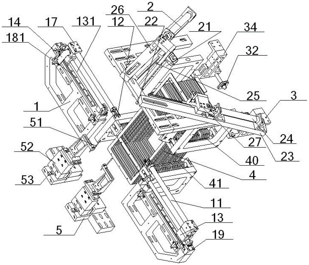
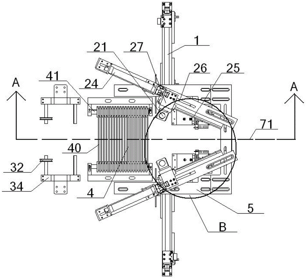
[0065] see figure 1 – Figure 13 , a three-dimensional weaving edge device, comprising a weft insertion mechanism 1, a weft thread sliding mechanism 2, an opening mechanism 4, and a weft thread fixing mechanism 5, the number of the weft insertion mechanism 1, the weft thread sliding mechanism 2, and the weft thread fixing mechanism 5 are two, The two weft sliding mechanisms 2 are symmetrically arranged with the horizontal central axis 71 as the line of symmetry, and the two weft insertion mechanisms 1 are symmetrically arranged with the horizontal central axis 71 as the line of symmetry. The connecting line between the two weft insertion mechanisms 1 and the weft insertion The travel lines of the mechanism 1 are coincident, and the two weft fixing mechanisms 5 are symmetrically arranged with the horizontal central axis 71 as the line of symmetry; the opening mechanism 4 includes a plurality of heald frames 40 arranged side by side and parallel to each other. The side of frame...

Embodiment 2

[0071] Basic content is the same as embodiment 1, the difference is:

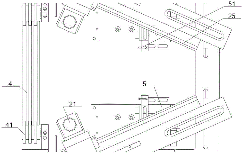
[0072] The weft sliding mechanism 2 also includes a sliding base 23, a horizontal sliding cylinder 24 and a linear guide rail 25, the top of the sliding base 23 is connected with the bottom of the horizontal sliding cylinder 24, and the output end of the horizontal sliding cylinder 24 is connected to the horizontal push rod 26 The inner end of the horizontal push rod 26 is connected to the top of the vertical support 27, and the inner side of the vertical support 27 is slidably matched with the linear guide rail 25 provided on the inner side of the sliding base 23. The vertical support The outer part of 27 is connected with the inner part of vertical telescopic cylinder 21, and the output end of vertical telescopic cylinder 21 is connected with the top of the vertical push rod 22 that is positioned at directly below it, and the bottom of vertical push rod 22 is provided with The vertical slot 28 is inserted...

Embodiment 3

[0074] Basic content is the same as embodiment 1, the difference is:

[0075]Described sideline device also comprises two latitude anti-band mechanisms 3, two weft anti-band mechanisms 3 are left and right symmetrically arranged with the horizontal axis 71 as the line of symmetry, each weft anti-band mechanism 3 all comprises anti-band lines 31, anti-band rollers 32 and the counterweight 33, one end of the anti-band line 31 is connected with the top of the counterweight 33 after the anti-band roller 32, the middle part of the anti-band roller 32 is connected with the anti-band support 34, and the other part of the anti-band line 31 One end is connected with the fixed frame 35, the position between the anti-belt roller 32 and the counterweight 33 on the anti-belt line 31 coincides with its center of gravity line, and the part between the anti-belt roller 32 and the fixed frame 35 on the anti-belt line 31 The position is parallel to the horizontal central axis 71, and the positi...


PUM


Abstract

A three-dimensional knitted side boundary device comprises an opening mechanism, a weft guiding mechanism, a weft sliding mechanism and a weft fixing mechanism. During use, the opening mechanism achieves warp opening through vertical stagger of different heald frames; the weft guiding mechanism enables weft to advance through a weft guiding rod and a weft guiding hook to pass through a weft opening, the weft sliding mechanism and the weft fixing mechanism drag the weft passing through the warp opening so that subsequent knitting and tightening can be facilitated, and especially when a weft taken preventing device is additionally arranged, the connection success rate of weft among vertical push rods and side boundary rods can be increased. The three-dimensional knitted side boundary device is simple in structure and high in working efficiency and precise control degree, the warp opening effect is good, the weft taken preventing function is good, and environment friendliness is good.

Description

technical field [0001] The invention relates to a three-dimensional weaving device, which belongs to the technical field of textiles, in particular to a three-dimensional weaving edge device and a method for using the same, and is particularly suitable for simplifying the structure of the device and improving work efficiency. Background technique [0002] In modern textile machinery, weaving machines play an important role. Clothes, bedding and other fabrics in people's daily life are inseparable from weaving machines. In the development process of knitting machines, two-dimensional knitting machines have a wide range of applications and are applied to various fields in the textile industry. With the development of science and technology, two-dimensional looms can no longer meet people's needs, and three-dimensional looms have emerged. The appearance of three-dimensional looms makes fabrics no longer limited to two-dimensional plane fabrics. It not only has X, Y axis yarns, ...

Claims


Application Information

Patent Timeline
Patent Type & Authority Applications(China)
IPC IPC(8): D03D41/00D03D47/27D03C13/00
CPCD03C13/00D03D41/004D03D47/27
Inventor 林富生龚小舟李宇
Owner 广东世纪金海复合材料有限公司
Why Eureka
Try Eureka