A device and method for removing sediment at the bottom of hole-forming cast-in-place piles

A cast-in-place pile and sediment technology, which is applied in earthwork drilling, drilling equipment, wellbore/well parts, etc., can solve the problems of high energy consumption and low removal efficiency, and achieve the effects of improving work efficiency, convenient operation and reducing costs

Active Publication Date: 2017-12-15
CHINA MCC5 GROUP CORP
View PDF6 Cites 1 Cited by
  • Summary
  • Abstract
  • Description
  • Claims
  • Application Information

AI Technical Summary

Problems solved by technology

[0005] The object of the present invention is to provide a device and method for removing the sediment at the bottom of the hole-forming cast-in-place pile, so as to solve the problem that the overall removal efficiency is not high and the energy consumption is relatively high when removing the sediment at the bottom of the hole-forming pile. high problem

Method used


Image

  • A device and method for removing sediment at the bottom of hole-forming cast-in-place piles
  • A device and method for removing sediment at the bottom of hole-forming cast-in-place piles
  • A device and method for removing sediment at the bottom of hole-forming cast-in-place piles

Examples


Embodiment 1

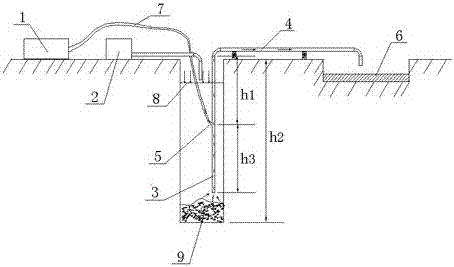
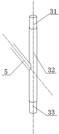
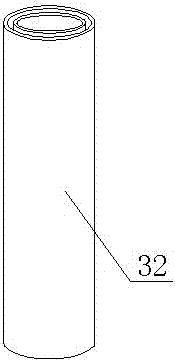
[0039] Such as figure 1As shown, a device for removing sediment at the bottom of a hole-forming cast-in-place pile described in this embodiment includes an air supply mechanism 1, a liquid delivery mechanism 2, a hose 7, and a slag discharge pipe, and the slag discharge pipe includes a slag discharge pipe The vertical part 3 and the horizontal part 4 of the slag discharge pipe, the vertical part 3 of the slag discharge pipe communicates with the air supply mechanism 1 through the hose 7, and the vertical part 3 of the slag discharge pipe includes an upper pipe 31, a middle pipe 32 and a lower pipe 33. The middle pipe 32 includes an outer pipe 321 and an inner pipe 322 whose central axes coincide. The upper pipe 31 is threaded with the outer pipe 321 or the inner pipe 322. The lower pipe 33 is also threaded with the outer pipe 321 or the inner pipe 322.

[0040] This embodiment also includes an inclined pipe 5 , which runs obliquely downward through the inner pipe and the outer...

Embodiment 2

[0050] Such as figure 2 As shown, on the basis of Embodiment 1, this embodiment has also made the following limitations: the included angle between the central axis of the inclined tube 5 and the central axis of the inner tube 322 in this embodiment is 15 to 20 degrees, and the inner tube 322 The ratio of the diameter to the diameter of the hose 7 is 3-5. After adopting such a design in this embodiment, the slurry-gas mixture is better produced under the same energy consumption, and it has a stronger power to bring the sediment out of the bottom of the hole, which improves the efficiency of slag removal and avoids Unnecessary energy consumption is produced.

Embodiment 3

[0052] Such as Figure 3~8 As shown, the present embodiment has been further designed on the basis of embodiment 1 or embodiment 2, specifically as follows:

[0053] The upper tube 31 itself is provided with a first external thread 34, the upper inner wall of the outer tube 321 is provided with an upper internal thread 36 that matches the first external thread 34, and the lower tube 33 is provided with a second external thread 35. The lower part of the inner wall of the pipe is provided with a lower internal thread 37 matched with the second external thread 35 . Through this design, the sediment enters the inner pipe from the lower pipe, and then enters the upper pipe until it is discharged from the slag discharge pipe. In this process, the sediment will not contact with each thread at all, thus ensuring that the thread is not affected by the sediment and can Maintaining a normal state for a long time facilitates the normal and rapid adjustment of the length of the slag disch...


PUM


Abstract

The invention discloses a device and a method for removing hole bottom sediment of a pore-forming pouring pile. The device comprises an air supply mechanism, a liquid supply mechanism, a hose, a sediment discharging pipe and an inclined pipe; the sediment discharging pipe comprises a vertical sediment discharging pipe part and a horizontal sediment discharging pipe part; the vertical sediment discharging pipe part is communicated with the air supply mechanism through the hose, and comprises an upper pipe, a middle pipe and a lower pipe; the middle pipe comprises an outer pipe and an inner pipe of which the central axes are overlapped; the upper pipe is connected with the outer pipe or the inner pipe through screw threads; the lower pipe is also connected with the outer pipe or the inner pipe through screw threads; the inclined pipe penetrates through the inner pipe and the outer pipe downwards; an air outlet of the air supply mechanism is communicated with the inner pipe through the hose and the inclined pipe in sequence. By adoption of the structure, the sediment removal efficiency is improved effectively, but energy consumption is not increased obviously.

Description

technical field [0001] The invention relates to the field of building construction, in particular to a device and method for removing sediment at the bottom of a hole-forming cast-in-place pile. Background technique [0002] The sediment thickness at the bottom of the bored pile is an important indicator of the construction quality control of the pile, which directly affects the bearing capacity of the pile, especially for the end-bearing pile and the friction end-bearing pile, which mainly bear the load at the pile end. Therefore, effective removal of sediment at the bottom of the hole is the key to controlling the quality of piles. At present, a large number of large-diameter and super-long cast-in-situ pile foundations are used in bridge design. Therefore, how to effectively control the thickness of sediment has always been a problem that plagues construction. [0003] At present, in order to remove the sediment at the bottom of the hole-forming cast-in-place pile, a gas...

Claims


Application Information

Patent Timeline
Patent Type & Authority Patents(China)
IPC IPC(8): E21B21/14E21B17/00E21B17/02
CPCE21B17/00E21B17/042E21B21/14
Inventor 喻绵俊罗利倪伟罗建勋陈明实
Owner CHINA MCC5 GROUP CORP
Why Eureka
Try Eureka