Booster-type oil tank

A fuel tank and pressurized pipe technology, which is applied in the direction of fuel supply tank devices, fluid pressure converters, mechanical equipment, etc., can solve the problems of poor boosting effect, low oil outlet pressure of the fuel tank, and low oil outlet efficiency, and achieve improved The effect of pressure, high flexibility, and easy installation and disassembly

Inactive Publication Date: 2016-06-08
WUXI HAIJUN HEAVY IND
View PDF4 Cites 4 Cited by
  • Summary
  • Abstract
  • Description
  • Claims
  • Application Information

AI Technical Summary

Problems solved by technology

The disadvantages of the traditional pressurized fuel tank are that the boost effect is not

Method used


Image

  • Booster-type oil tank

Examples


Example Embodiment

[0009] The specific embodiments of the present invention will be further described below in conjunction with the accompanying drawings.

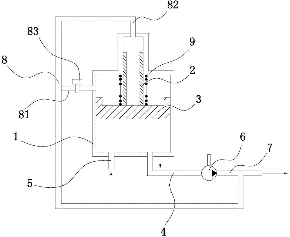
[0010] Such as figure 1 As shown, the pressurized oil tank of this embodiment includes a box body 1, a piston 3 installed in the box body 1, a piston rod 2 is installed at the upper end of the piston 3, and an oil outlet pipe 4 and an oil return pipe 5 are connected to the bottom surface of the oil tank 1. The oil pipe 4 is connected to the hydraulic pump 6, the hydraulic pump 6 is connected to the output pipe 7, and the output pipe 7 has a booster pipe 8. The booster pipe 8 is respectively connected to the first branch pipe 81 connected with the oil tank 1 and the second branch pipe connected with the piston rod 2 82, the outer wall of the piston rod 2 is provided with a spring 9, the upper and lower ends of the spring 9 are respectively connected to the inner wall of the box 1 and the piston 3, and a flow control valve 83 is connected to the ...


PUM


Abstract

The invention relates to a booster-type oil tank. The oil tank comprises a tank body and a piston arranged in the tank body; a piston rod is arranged at the upper end of the piston, and the bottom face of the oil tank is connected with an oil outlet pipe and an oil returning pipe; the oil outlet pipe is connected with a hydraulic pump, and the hydraulic pump is connected with an output pipe; the output pipe is provided with a booster pipe, and the booster pipe is connected with a first branch pipe communicated with the oil tank and a second branch pipe communicated with the piston rod; a spring is arranged on the outer wall of the piston rod, the upper end of the spring is connected with the inner wall of the tank body, and the lower end of the spring is connected with the piston of the tank body; and a flow control valve is connected to the first branch pipe. The booster pipe and the spring are additionally arranged on the oil tank, and therefore the pressure of the piston is increased; pressure of hydraulic oil in the oil tank is improved, and the flow control valve is arranged so that the booster degree of the oil tank can be adjusted; the beneficial effect of being high in flexibility is achieved; and the spring is arranged on the outer wall of the piston rod, and mounting and dismounting are convenient.

Description

Technical field: [0001] The invention relates to the field of hydraulic equipment, in particular to an oil tank of a hydraulic system. Background technique: [0002] In the hydraulic system, the oil tank is mainly used for oil storage, heat dissipation and separation of air and impurities in the hydraulic oil. The design of the oil tank directly affects the reliability of hydraulic components and systems, especially the life of the hydraulic pump. For the environment with high altitude or low air pressure, if a general open oil tank is used, the inlet pressure of the hydraulic pump will often be reduced and cause cavitation of the hydraulic pump, which will seriously affect the normal operation of the hydraulic system. Therefore, it is necessary to use a booster type Fuel tank, the pressurized fuel tank can increase the pressure on the oil surface of the fuel tank to prevent cavitation of the hydraulic pump, thereby effectively improving the high-altitude performance of the...

Claims


Application Information

Patent Timeline
IPC IPC(8): F15B1/26F15B3/00
Inventor 朱龙
Owner WUXI HAIJUN HEAVY IND
Why Eureka
Try Eureka