
Infrared sensing electronic whiteboard

An infrared sensing and electronic whiteboard technology, which is applied in the input/output process of electronic digital data processing, instruments, and data processing, etc. The structure is not complicated and the cooling effect is balanced

Inactive Publication Date: 2016-06-08
NANJING INST OF RAILWAY TECH
View PDF5 Cites 0 Cited by
  • Summary
  • Abstract
  • Description
  • Claims
  • Application Information

AI Technical Summary

Problems solved by technology

[0007] In addition, the controller part, infrared signal transmitting and receiving part, and signal processing part are often placed in the control cabinet, so that the controller part, infrared signal transmitting and receiving part, and signal processing part tend to heat up in such a relatively closed environment. However, the method of air supply from the upper end and air discharge from the bottom is generally used to cool the controller part, infrared signal transmitting and receiving part, and signal processing part, which will make the high-temperature gas flow toward the high place, thus making the ultra-high The high-temperature gas flowing at the bottom is drawn into the bottom again, which makes the cooling efficiency unsatisfactory; combined with the structure of the intake fan intake, the low-temperature gas in the environment where the control cabinet is located is sent into the various components of the control cabinet, so that the gas The distribution is uneven, but setting a stopper in the gas passage will make the structure complicated. In addition, it can only make the gas around the stopper evenly distributed. The current anti-leakage structure uses rubber bonded gaskets, which often makes parts of the anti-leakage structure fall off. from the problem

Method used


Image

  • Infrared sensing electronic whiteboard
  • Infrared sensing electronic whiteboard
  • Infrared sensing electronic whiteboard

Examples


Embodiment Construction

[0020] Below in conjunction with accompanying drawing and embodiment, content of the invention will be further described:

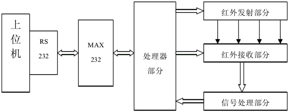
[0021] refer to Figure 1-Figure 7 As shown, the infrared sensing electronic whiteboard includes a host computer with an RS232 interface, the RS232 interface is connected with the MAX232 chip, and the MAX232 chip is also connected with the processor part, and the processor part is also connected with the infrared emitting part, The infrared receiving part and the signal processing part are connected, and the infrared emitting part, the infrared receiving part and the signal processing part are connected sequentially, and the infrared receiving part includes several infrared receiving tubes, and the processor part, the infrared emitting part, the infrared The receiving part and the signal processing part are set in the control cabinet A9;

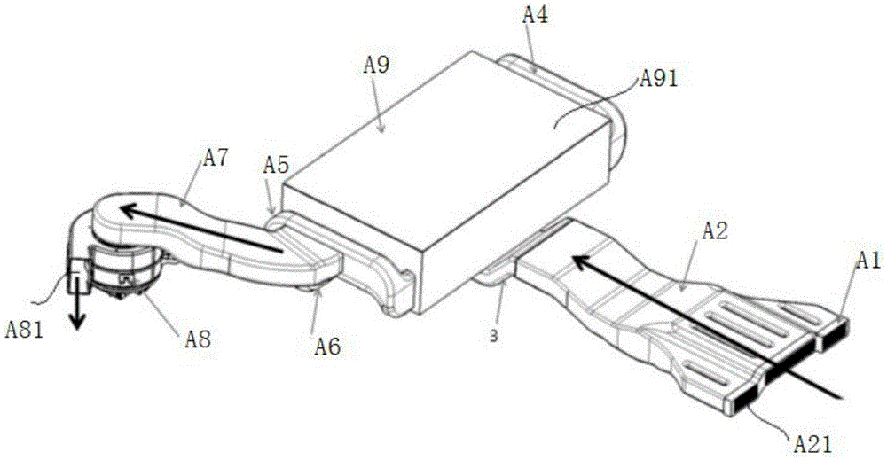
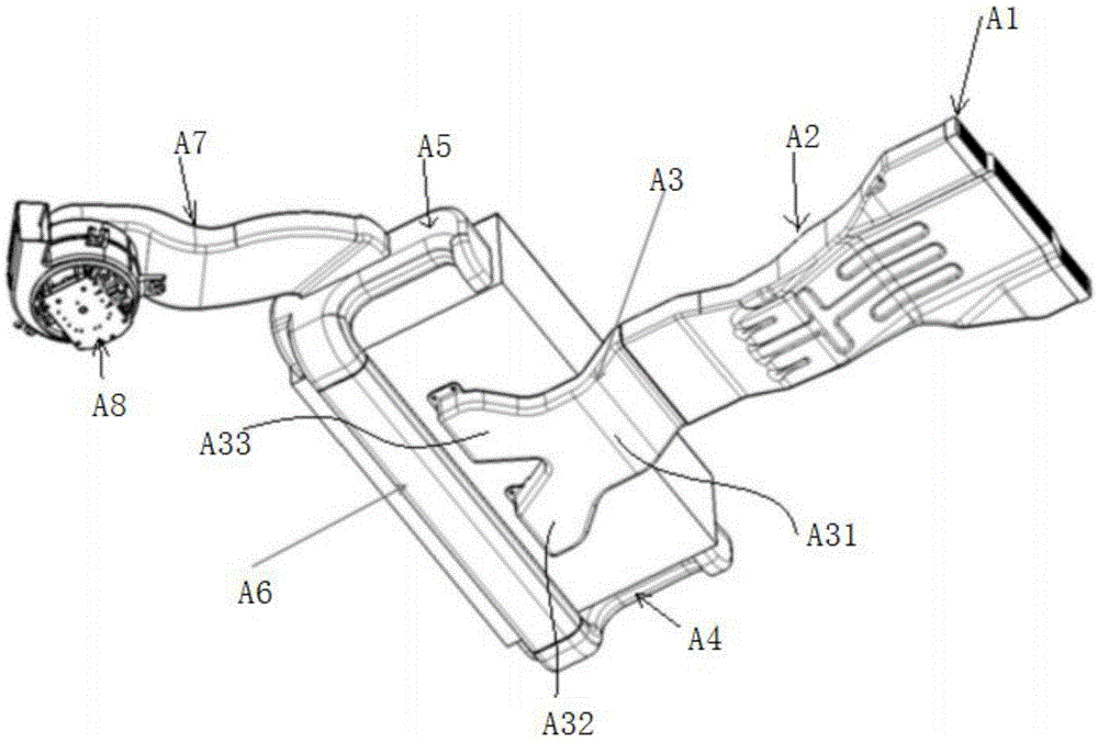
[0022]In addition, it also includes a cavity passage for feeding gas, a cavity passage for releasing gas, the first ...


PUM


Abstract

The invention discloses an infrared sensing electronic whiteboard. An RS232 interface is connected with an MAX232 chip, wherein the MAX232 chip is further connected with a processor part; the processor part is further connected with an infrared emitting part, an infrared receiving part and a signal processing part; the infrared emitting part, the infrared receiving part and the signal processing part are connected in sequence; the infrared receiving part comprises a plurality of infrared receiving tubes; the processor part, the infrared emitting part, the infrared receiving part and the signal processing part are arranged in a control cabinet; in addition, the infrared sensing electronic whiteboard further comprises a cavity passage I for feeding a gas, a cavity passage II for discharging the gas, as well as a first supporting base and a second supporting base for positioning the processor part, the infrared emitting part, the infrared receiving part and the signal processing part; the infrared sensing electronic whiteboard overcomes the defects in the prior art that the refrigerating efficiency is not ideal, the gas distribution is not uniform, the structure is complex, and an anti-leakage structure has components falling off.

Description

technical field [0001] The invention belongs to the technical field of electronic whiteboards, and in particular relates to an infrared induction electronic whiteboard. Background technique [0002] Infrared induction electronic whiteboard, that is, infrared positioning electronic whiteboard system, its hardware circuit is composed of controller, infrared transmitting circuit, infrared receiving circuit, infrared signal processing circuit and communication circuit with host computer. [0003] 1. Controller part: including the peripheral circuit and interface of the single-chip microcomputer. [0004] 2. Infrared signal transmitting and receiving part: The controller drives the infrared emitting strobe circuit and the infrared receiving strobe circuit according to the scanning method adopted, and selects each infrared emitting tube and infrared receiving tube in turn. [0005] 3. Signal processing part: several processes of filtering, amplification, detection, integration an...

Claims


Application Information

Patent Timeline
IPC IPC(8): G06F3/042
CPCG06F3/042
Inventor 王啸东
Owner NANJING INST OF RAILWAY TECH
Features
  • Generate Ideas
  • Intellectual Property
  • Life Sciences
  • Materials
  • Tech Scout
  • Unparalleled Data Quality
  • Higher Quality Content
  • 60% Fewer Hallucinations
Learn More