Multi-band antenna and mobile terminal

A multi-band antenna and frequency band technology, applied to antennas, devices that enable antennas to work in different bands at the same time, electrical components, etc., can solve the problem that the antenna cannot work in multiple frequency bands at the same time, and can only send and receive signals in one frequency band

Inactive Publication Date: 2016-06-08
GUANGDONG OPPO MOBILE TELECOMM CORP LTD
View PDF6 Cites 4 Cited by
  • Summary
  • Abstract
  • Description
  • Claims
  • Application Information

AI Technical Summary

Problems solved by technology

[0004] The embodiment of the present invention provides a multi-band antenna to solve the problem in the prior art that the antenna cannot work in multiple frequency bands at the same time; the embodiment of the present invention also provides a mobile terminal, the mobile terminal adopts the multi-band antenna of the present invention antenna, so that the mobile terminal of the present invention can simultaneously send and receive multiple frequency band signals, solving the problem in the prior art that only one frequency band signal can be sent and received at the same time

Method used


Image

  • Multi-band antenna and mobile terminal
  • Multi-band antenna and mobile terminal
  • Multi-band antenna and mobile terminal

Examples


Embodiment Construction

[0026] In order to illustrate the embodiments of the present invention or the technical solutions in the prior art more clearly, the drawings that need to be used in the embodiments are briefly introduced below. The drawings in the following description are only part of the embodiments of the present invention, and those skilled in the art can obtain other drawings according to these drawings without creative work.

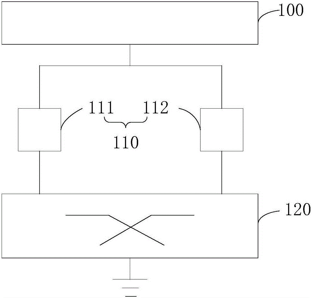
[0027] See figure 1 , figure 1 It is a structural schematic diagram of the multi-band antenna in the first preferred embodiment of the present invention. In this preferred embodiment, the multi-band antenna includes: an antenna body 100 , a matching circuit 110 and a frequency divider 120 .

[0028] The antenna body 100 is used for receiving and sending signals, and at least includes a ground feed point.

[0029] Matching circuit 110, which includes a plurality of matching sub-circuits, a plurality of matching sub-circuits can be divided according to different ...


PUM


Abstract

The invention provides a multi-band antenna and a mobile terminal. The multi-band antenna comprises an antenna body, matching circuits and a frequency demultiplexer, wherein each matching circuit comprises multiple matching subcircuits, one end of each matching subcircuit is connected with a ground wire feeding point or a signal feeding point of the antenna body, the other end of each matching subcircuit is respectively connected with input interfaces for corresponding frequency bands of the frequency demultiplexer, and the matching circuit is used for modulating antenna input impedance of the antenna body during operation in a corresponding frequency band; and the frequency demultiplexer is used for separating signals which are received or transmitted by the antenna body and at different frequencies. The multi-band antenna provided by the embodiments of the invention has the advantages that the frequency demultiplexer is arranged in the multi-band antenna and separates the signals which are received or transmitted by the antenna and at different frequencies, so that the signals at different frequencies pass through different matching circuits, the input impedance of the antenna is modulated, the antenna works in different frequency bands at the same time, and requirements of CA on multiple frequency bands and multiple combinations are met.

Description

technical field [0001] The invention relates to the technical field of antennas, in particular to a multi-band antenna and a mobile terminal using the multi-band antenna. Background technique [0002] With the development of 4G network, there are more and more frequency bands around the world, from low frequency 700MHz, to medium frequency 2GHz, to high frequency 2.6GHz. Coupled with the requirement of carrier aggregation (English name CarrierAggregation, referred to as CA) in the long-term evolution technology (English name LongTermEvolution technology, referred to as LTE technology), several different LTE frequency bands are required to work at the same time. Moreover, there are more and more types of CA combinations, such as CA combinations of low-frequency bands and mid-bands, CA combinations of low-frequency bands and high-frequency bands, etc. These combinations have high requirements for antennas. [0003] In order to realize the multi-band operation of the antenna, ...

Claims


Application Information

Patent Timeline
Patent Type & Authority Applications(China)
IPC IPC(8): H01Q5/00
CPCH01Q5/00
Inventor 杨金胜
Owner GUANGDONG OPPO MOBILE TELECOMM CORP LTD
Why Eureka
Try Eureka