
Channel loaded bowknot type electromagnetic forbidden band antenna

A technology of electromagnetic bandgap antenna and electromagnetic bandgap structure, which is applied in directions such as antennas, resonant antennas, and mid-position feeding between antenna terminals, which can solve the problems of complex structure and difficult to achieve optimal parameter control, and achieve impedance and radiation patterns. Stable, good gain, the effect of expanding the antenna impedance bandwidth

Inactive Publication Date: 2009-04-01
重庆工学院
View PDF1 Cites 4 Cited by
  • Summary
  • Abstract
  • Description
  • Claims
  • Application Information

AI Technical Summary

Problems solved by technology

However, the above-mentioned prior art has disadvantages such as complex structure and difficulty in optimal parameter control.

Method used


Image

  • Channel loaded bowknot type electromagnetic forbidden band antenna
  • Channel loaded bowknot type electromagnetic forbidden band antenna
  • Channel loaded bowknot type electromagnetic forbidden band antenna

Examples


Embodiment Construction

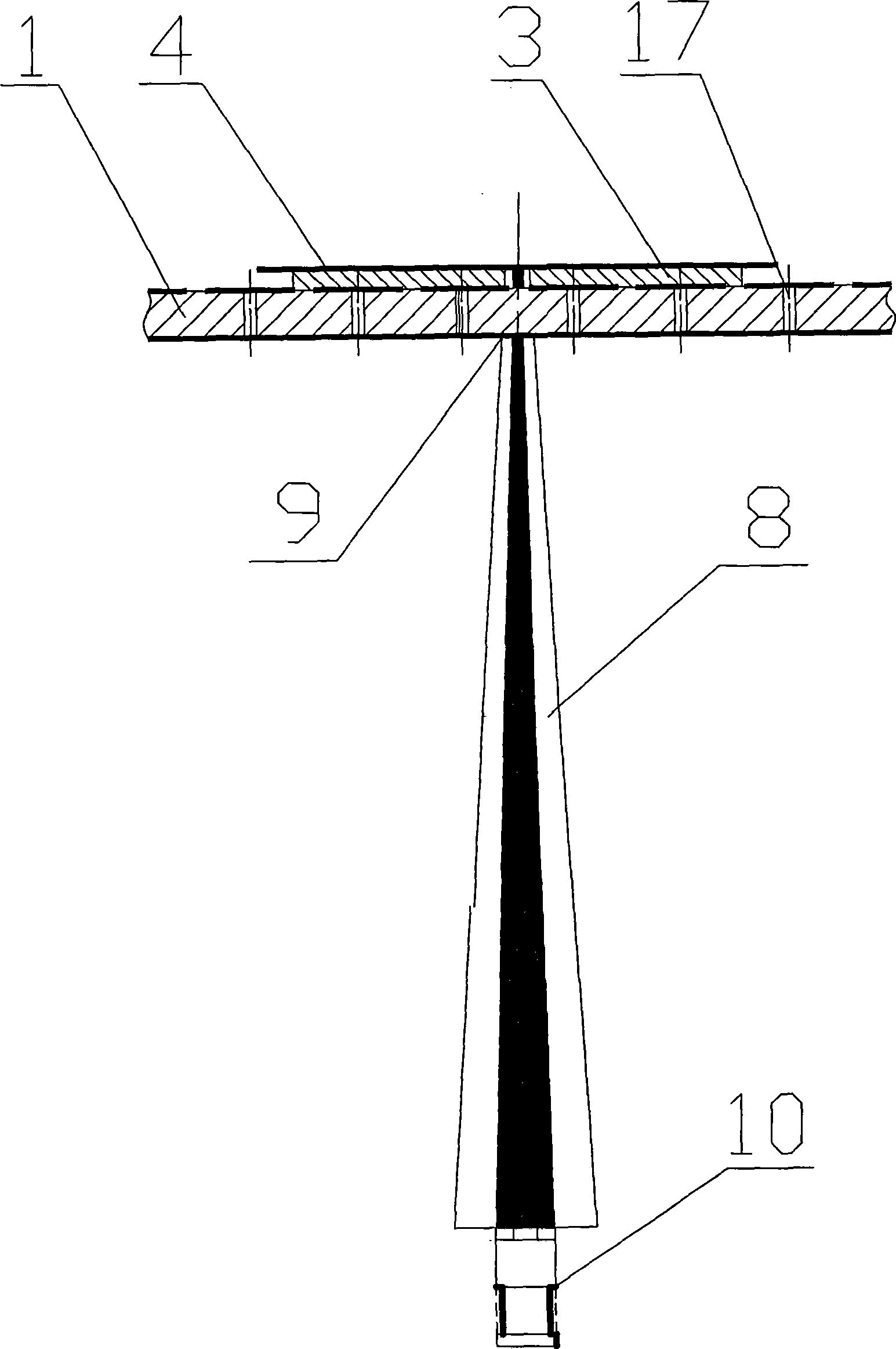
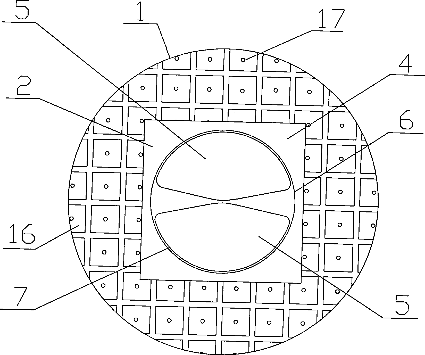
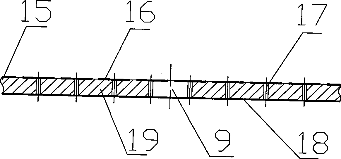
[0021] Such as figure 1 , 2 Middle, 1—electromagnetic bandgap structure, 2—bow tie antenna, 3—support layer, 4—Rogers substrate, 5—butterfly arm, 6—antenna loop, 7—loading channel, 8—balun, 9—through hole , 10—SMA;

[0022] The channel-loaded bow-tie type electromagnetic bandgap antenna of the present invention comprises an electromagnetic bandgap structure 1, and the bowtie antenna 2 is supported by a supporting layer 3, and is arranged on the electromagnetic bandgap structure 1; A foam-like material with a constant of about 1. A kind of specific embodiment structure of bowtie antenna 2 is: bowtie antenna 2 is made on the Rogers substrate 4 that relative permittivity is 2.2, and thickness is 0.508 millimeter, is provided with symmetrical two butterfly arms 5, antenna ring 6 and loading The channel 7, the butterfly arm 5 and the antenna ring 6 are made of metal (preferably copper and copper alloy, etc.), capable of receiving and radiating electromagnetic waves; the Rogers s...


PUM


Abstract

The invention discloses a channel loaded bow-tie electromagnetic band gap antenna which comprises an electromagnetic band gap structure. The antenna is characterized in that: the bow-tie antenna is supported by a supporting layer and is arranged on the electromagnetic band gap structure; one end of a Balun is connected with the bow-tie antenna to feed current to the bow-tie antenna by passing through a through hole arranged in the center of a substrate of the electromagnetic band gap structure, and the other end is connected with an SMA. In the antenna, capacitive load and inductive load can realize self-balance in broad frequency band, and the impedance and the radiation mode in the antenna are stable, thus expanding the impedance bandwidth of the antenna; and the antenna gain is not affected while expanding the operation bandwidth of the antenna; the distance between the antenna and the electromagnetic band gap structure can be rather less than a quarter wavelength, and broad operating frequency range and good gain can be acquired.

Description

technical field [0001] The invention relates to the technical field of wireless communication, in particular to a channel-loaded bow-tie electromagnetic bandgap antenna. Background technique [0002] In recent years, many technologies for widening the impedance bandwidth of planar antennas have been frequently reported, such as impedance loading technology, RC loading technology, folding technology, zigzag technology, multi-feed point technology and short-circuit pin technology, etc. These technologies can broaden the working bandwidth of the antenna to a certain extent, but some are concentrated loading technologies, which will bring about a decrease in antenna gain, such as impedance loading and RC loading technologies; some make the antenna structure complex, parameter control is difficult to achieve optimal, and design is difficult Larger, such as folding technology, zigzag technology, multi-feed point technology and short-circuit pin technology. [0003] For applicatio...

Claims


Application Information

Patent Timeline
Patent Type & Authority Applications(China)
IPC IPC(8): H01Q1/38H01Q9/16H01Q13/00
Inventor 丁朝远
Owner 重庆工学院
Learn More