Spreader tip for a rescue tool

A dilator and device head technology, applied in life-saving equipment, building rescue, shackles, etc., can solve the problem of not meeting all the requirements of the characteristics of the dilator head, and achieve high bending strength, material properties optimization, high compressive strength. Effect

Active Publication Date: 2016-06-08
WEBER HYDRAULIK GMBH
View PDF4 Cites 7 Cited by
  • Summary
  • Abstract
  • Description
  • Claims
  • Application Information

AI Technical Summary

Problems solved by technology

[0003] The embodiment described in AT010110U1 has the disadvantage that, when selecting the material for the dilator head, it is not possible to meet all the requirements imposed on the properties of the dilator head

Method used


Image

  • Spreader tip for a rescue tool
  • Spreader tip for a rescue tool
  • Spreader tip for a rescue tool

Examples


Embodiment Construction

[0028] First of all, it should be ensured that, in the different described embodiments, the same components are denoted by the same reference numerals or the same component names, and the disclosure content contained in the whole specification can be reasonably transferred to the same reference numerals or the same component names. The same part of the assembly name. The position descriptions used in the description, such as top, bottom, side, etc., refer to the current description and the drawings shown and are reasonably transferable to the new position when the position is changed.

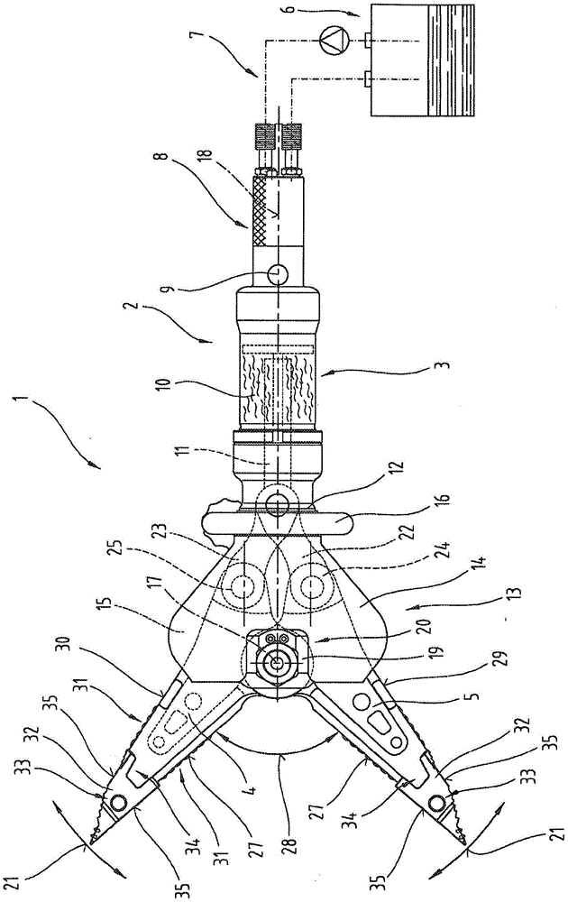
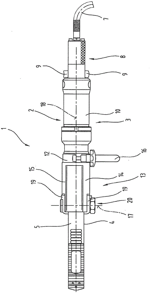
[0029] exist figure 1 and 2 Shown is a rescue device 1 with adjustable pincer-type expansion arms 4 , 5 which are adjustable on a cylinder 3 by means of a linear drive 2 .

[0030] In the embodiment shown, the drive device 2 consists of a hydraulic device 6 with a supply and discharge line 7 and a tubular handle 8 with a control device 9 integrated therein and a hydraulic cylinder with an adj...


PUM


Abstract

The invention relates to a spreader tip (32) for replaceable attachment to two pincer-like co-operating spreader arms (4) of a rescue tool (1). Mounted on a working face (35) of the spreader tip (32) is at least one insert element (39) which protrudes from and has different material properties in comparison with the spreader tip (32).

Description

technical field [0001] The present invention relates to a dilator head as given in claims 1 and 16 and to a rescue device equipped with such a dilator head. Background technique [0002] The applicant's patent application AT010110U1 discloses a rescue device with a clamp-type expansion arm, which has a surface area, at least on the inner sides of the expansion arms facing each other, which is larger than the adjacent ones. The abrasion resistance of the part is the abrasion resistance. Furthermore, the surface of the expansion arm in the region of the active surface on the object is provided with a protruding profile in order to prevent sliding relative to the object with high resistance. In addition, a replaceable dilator head is provided on the end of the dilator arm, which dilator head is made of a high-strength and wear-resistant, preferably quenched and tempered material. The spreader head is made of such a material because a high resistance should also be exerted on ...

Claims


Application Information

Patent Timeline
Patent Type & Authority Applications(China)
IPC IPC(8): A62B3/00
CPCA62B3/005F16G15/06
Inventor P·赫维希J·施莫伦格鲁伯K·施特罗迈尔
Owner WEBER HYDRAULIK GMBH
Why Eureka
Try Eureka