
A micro turbine generator

A technology of micro-generator and micro-turbine, which is applied in the field of micro-motors, can solve the problems of high misfire rate of bullets, complicated process, and inapplicability to mass production and processing, etc., so as to reduce the number of via holes, increase the number of coil turns, and improve the effective The effect of using the area

Inactive Publication Date: 2014-01-01
BEIJING INSTITUTE OF TECHNOLOGYGY
View PDF0 Cites 2 Cited by
  • Summary
  • Abstract
  • Description
  • Claims
  • Application Information

AI Technical Summary

Problems solved by technology

The mechanical trigger fuze uses a needle firing mechanism, and its disadvantages are: affected by the characteristics of the mechanical structure, it is difficult to improve the reliability of firing, which is manifested by a high rate of bullet misfire (about 5%)
Its disadvantages are: ① the process is complex, not suitable for mass production and processing; ② its structure is not suitable for bullet fuze

Method used


Image

  • A micro turbine generator
  • A micro turbine generator
  • A micro turbine generator

Examples


Embodiment Construction

[0030] The content of the present invention will be described in detail below in conjunction with the accompanying drawings and specific embodiments.

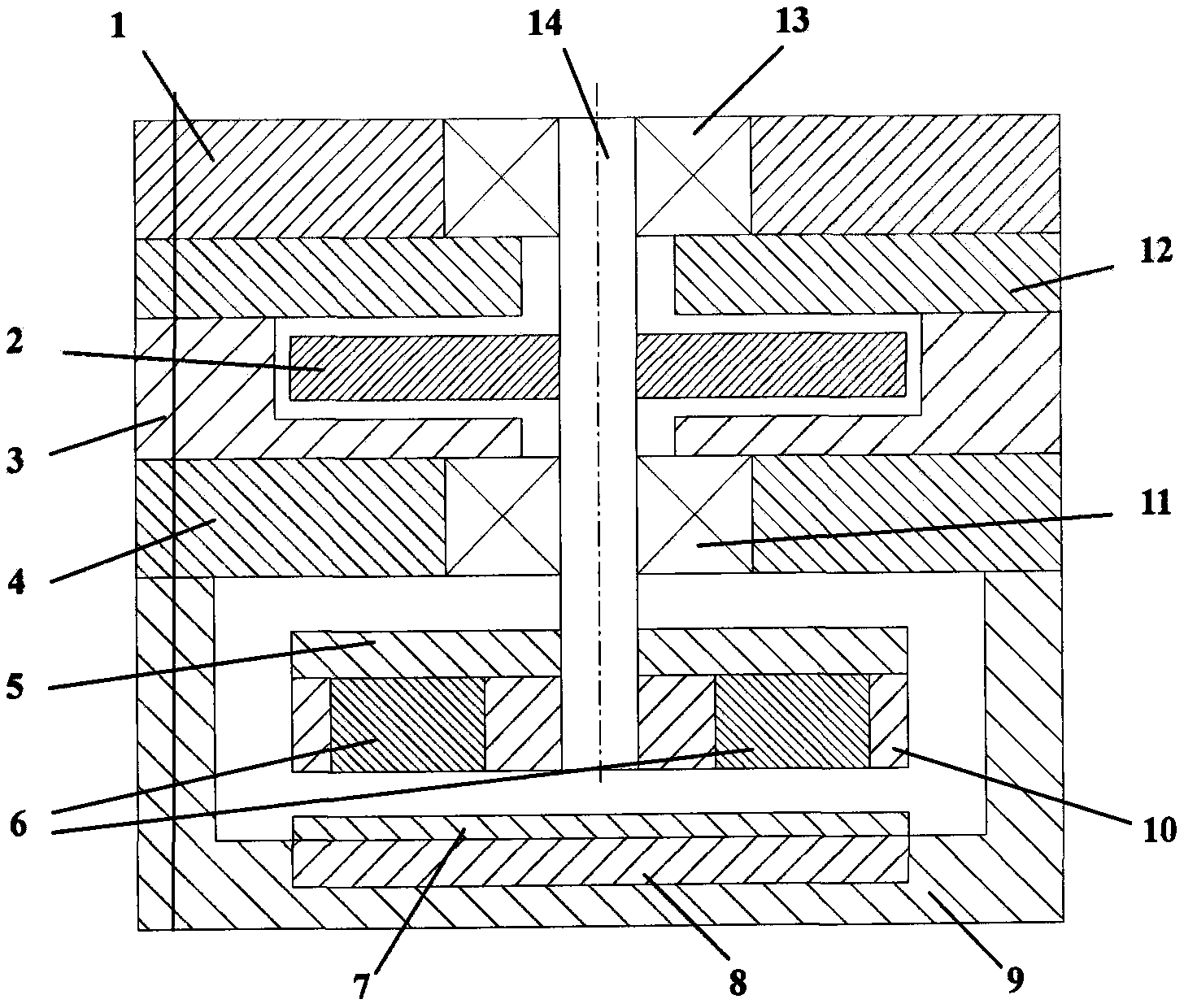
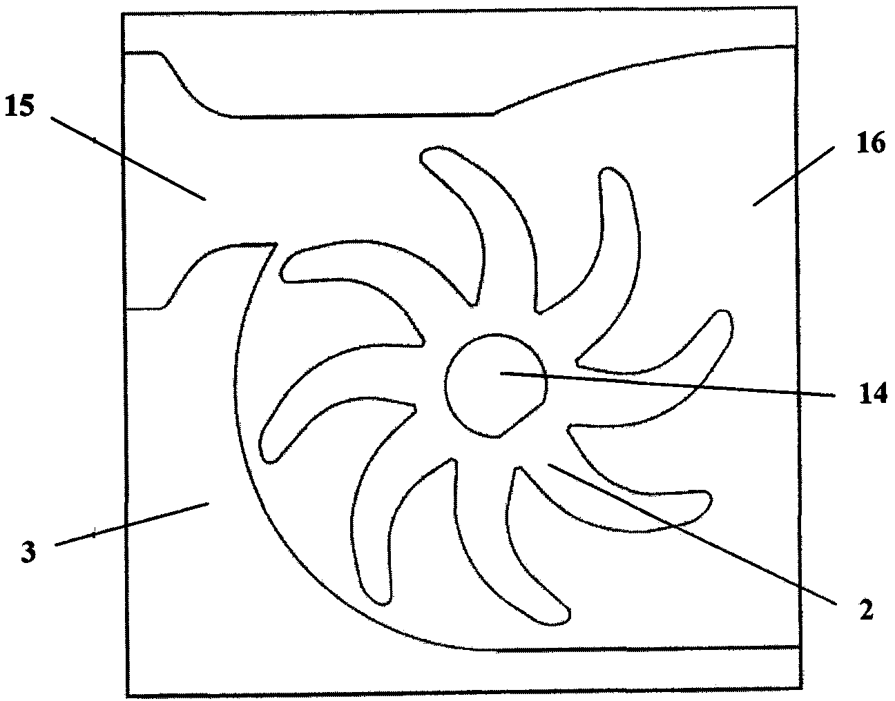
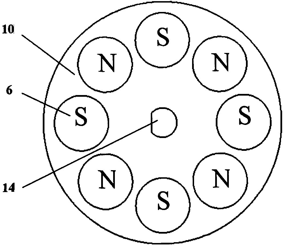
[0031] Install a micro-turbine generator in the bullet fuze of a certain sub-munition, and the volume needs to reach 1cm 3 Below, the output power reaches more than 1mW. To meet the above requirements, a micro-turbine generator is designed, such as figure 1 As shown, it includes: upper end cover 1, turbine 2, cavity 3, lower partition 4, rotor yoke 5, permanent magnet 6, flexible circuit board 7, stator yoke 8, lower end cover 9, rotor base plate 10, lower bearing 11. Upper partition 12, upper bearing 13, rotating shaft 14, air inlet 15, exhaust port 16, B-phase coil via hole 17, A-phase coil pad 18, C-phase coil via hole 19, A-phase coil 20, Through hole 21 , B-phase coil 22 , C-phase coil 23 .

[0032] A microturbine generator, such as Figure 1 to Figure 6 As shown, it includes four parts: a micro-pneumatic turbine, a mic...


PUM


Abstract

The present invention relates to a microturbine generator, comprising: ① micro pneumatic turbine: including a cavity, a turbine, and an upper baffle; the cavity and the upper baffle form a gas passage; ② micro generator: including a stator and a rotor; Composed of circuit board and stator yoke, the stator yoke is embedded in the lower end cover, the coil is processed on the flexible circuit board, and the flexible circuit board is attached to the exposed side surface of the stator yoke: the rotor is composed of the rotor yoke, the rotor base plate and the permanent magnet Composition; ③ transmission device: including rotating shaft, upper bearing and lower bearing; the fixed connection between the turbine and the rotating shaft, and the fixed connection between the rotating shaft and the rotor; ④ housing: the rotating shaft is connected to the upper end cover of the housing through the upper bearing, and the It is connected with the lower partition of the casing, and plays the role of fixing the rotating shaft and transmitting the power of the rotating shaft. The invention is suitable for the power supply device of the bullet fuze of the artillery sub-communication ammunition and other equipments requiring the miniature power supply device.

Description

technical field [0001] The invention relates to a microturbine generator, which is suitable for the power supply device of the bullet fuze of artillery sub-communication ammunition and other equipment requiring a micro power supply device, and belongs to the field of micro motors. Background technique [0002] The bullet fuze of my country's existing artillery sub-munitions is small in size and does not have enough space to install a power supply unit, so a mechanical trigger fuze is used. The mechanical trigger fuze uses a needle firing mechanism, and its disadvantage is that it is difficult to improve the reliability of firing due to the influence of mechanical structure characteristics, which is manifested in a high misfiring rate of bullets (about 5%). Under the international background that many countries in the world propose to limit the use of sub-munitions, it is particularly important to reduce the misfire rate of sub-munitions. [0003] An important way to reduce ...

Claims


Application Information

Patent Timeline
Patent Type & Authority Patents(China)
IPC IPC(8): F03D9/00
Inventor 孙韶春石庚辰王倩倩薛源郑华银
Owner BEIJING INSTITUTE OF TECHNOLOGYGY
Learn More