Open-loop fiber optic gyroscope signal detection method using 3×3 coupler

A technology of signal detection and fiber optic gyroscope, applied in the direction of Sagnac effect gyroscope, etc., can solve the problems of occupying microprocessor storage space, difficult temperature compensation, not easy to determine, etc., to reduce asymmetry and benefit cost , the effect of reducing the workload

Active Publication Date: 2005-09-21
BEIJING AEROSPACE TIMES OPTICAL ELECTRONICS TECH
View PDF1 Cites 1 Cited by
  • Summary
  • Abstract
  • Description
  • Claims
  • Application Information

AI Technical Summary

Problems solved by technology

The disadvantage of using this signal detection model is that the parameters in the model are very complicated, and it is not easy to determine the cause of the change when the parameters change. In addition, due to the close correlation between the coefficients, it brings difficulties to temperature compensation.
In addition, the deficiencies of the temperature compensation method disclosed in the flying missile are: there are too many temperature points to be measured, and the workload is very large; storing the corresponding coefficients of all temperature points in the microprocessor takes up a large amount of time for the microprocessor. of storage space

Method used


Image

  • Open-loop fiber optic gyroscope signal detection method using 3×3 coupler
  • Open-loop fiber optic gyroscope signal detection method using 3×3 coupler
  • Open-loop fiber optic gyroscope signal detection method using 3×3 coupler

Examples


Embodiment Construction

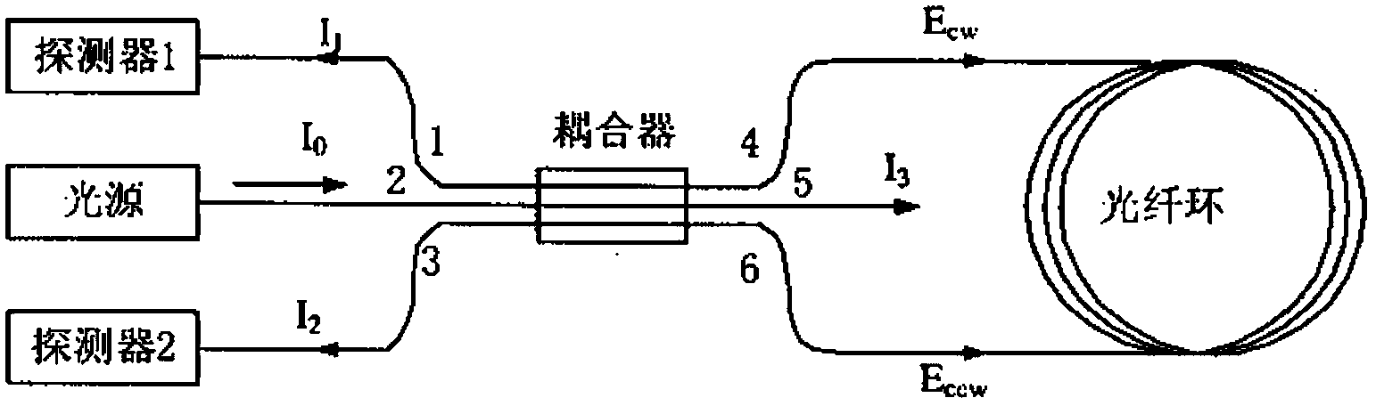
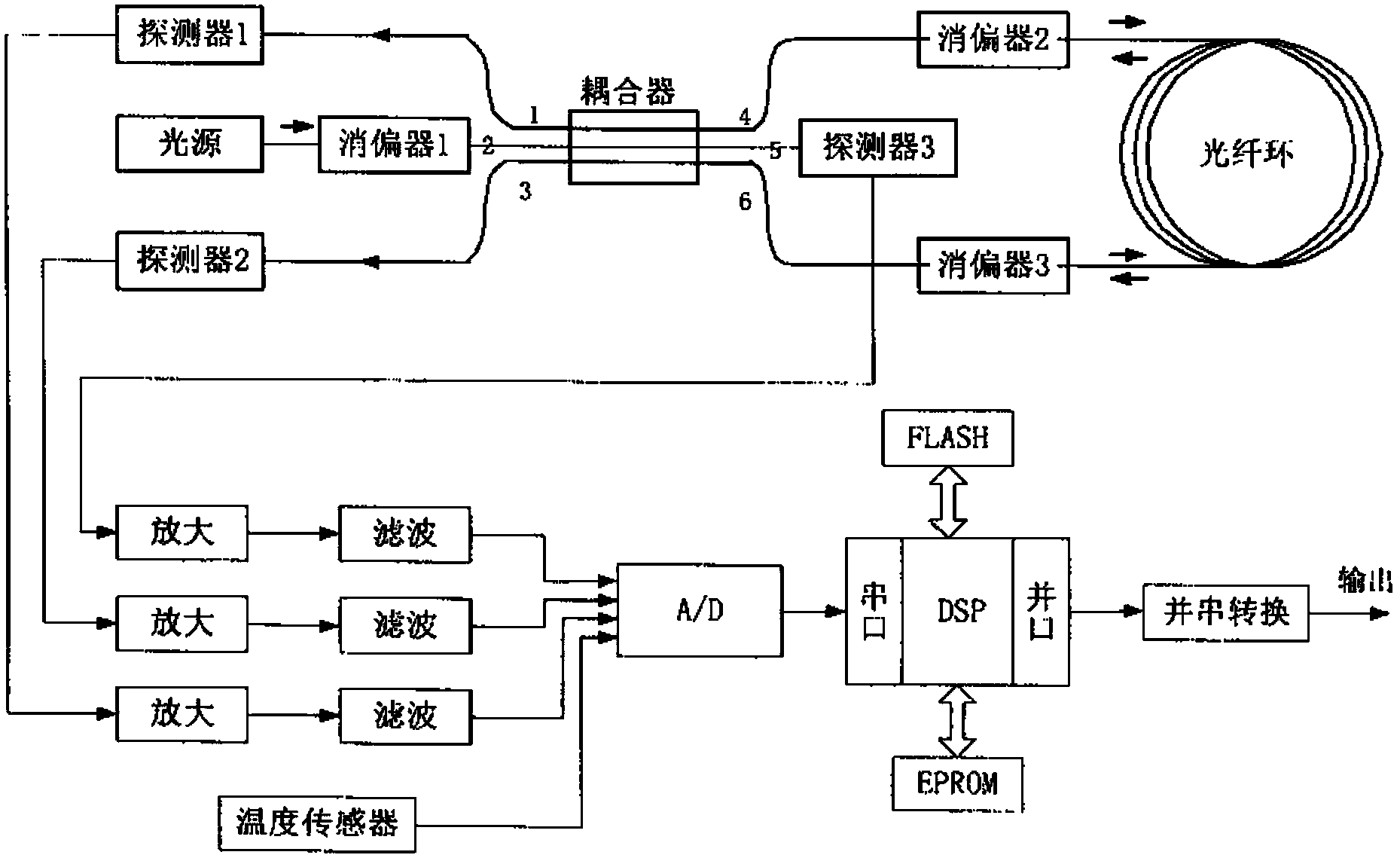
[0055] Such as figure 2 As shown, from the light source I 0 The emitted light enters the coupler through port 2 of the 3×3 coupler, and exits from ports 4, 5, and 6 of the coupler respectively. The clockwise (CCW) direction is transmitted in the fiber optic coil, then returns to the coupler and interferes, and the interference light is respectively detected by the detector D 1 and D 2 detection, detector D 1 and D 2 The outputs are P 1 and P 2 , the light exiting port 5 is detected by the detector D 3 detection, detector D 3 The output is P 3 .

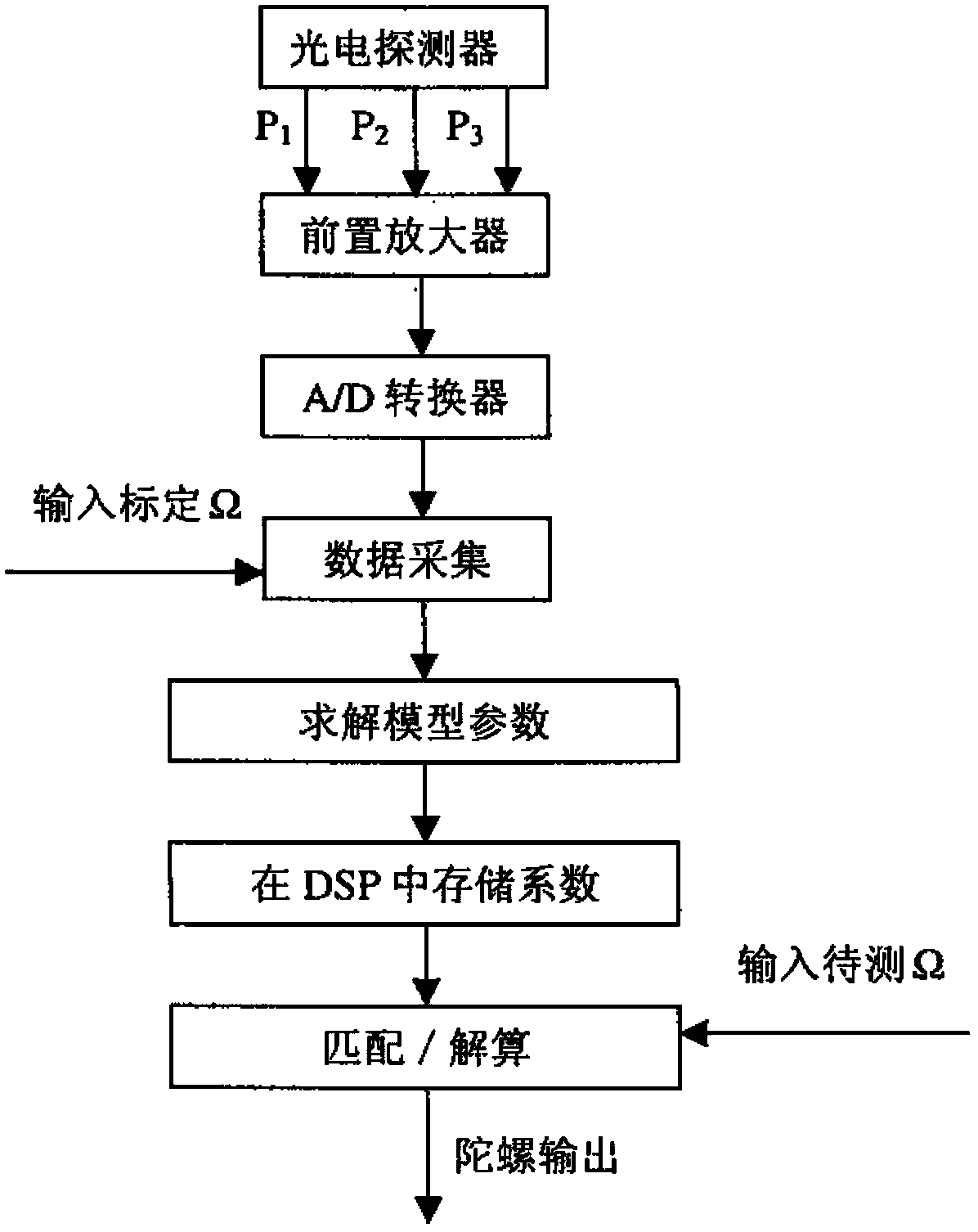
[0056] Such as image 3 Shown, the concrete detection step of the present invention is as follows:

[0057] (1) After the output of the three detectors of the gyro is amplified and filtered, the output P of the detectors at different rates is collected by the DSP system 1 ,P 2 ,P 3 , the selected rate points are ±0.05, ±0.1, ±1, ±5, ±10, ±20, ±40, ±60, ±80, ±100, ±120, ±150;

[0058] (2) The P corresponding to differen...


PUM


Abstract

The open-loop fiber optic gyroscope signal detection method using 3×3 couplers is characterized in that three detectors are used in the signal detection system, and the signal detection model is obtained by accurately analyzing the signals of the detectors.

Description

Technical field [0001] The invention relates to a signal detection method of an open-loop fiber optic gyroscope using a 3*3 coupler. Background technique [0002] At present, fiber optic gyroscope technology is mainly developed in two directions: improving accuracy and reducing cost. High-precision fiber optic gyroscopes generally adopt closed-loop solutions, while low-cost fiber optic gyroscopes mostly adopt open-loop solutions. Whether it is an open-loop or a closed-loop fiber optic gyroscope, most of them adopt a minimum reciprocity structure, and a 2×2 coupler is used as a beam splitter in the optical path. The characteristic is that bias modulation is required to improve the sensitivity near zero rotation speed of the gyroscope. Adding a reciprocal bias phase modulator in the optical path not only increases the complexity of the system, but also inevitably introduces noise. In the field of low precision, there is a good solution to this problem, which is to use 3×3 cou...

Claims


Application Information

Patent Timeline
Patent Type & Authority Patents(China)
IPC IPC(8): G01C19/72G01C19/64
Inventor 王巍张桂才杨清生李晶王学锋
Owner BEIJING AEROSPACE TIMES OPTICAL ELECTRONICS TECH
Why Eureka
Try Eureka