
Automatic Calibration Method and System for Scanning Accuracy of Ultrasonic Probe

An ultrasonic probe and automatic calibration technology, applied in ultrasonic/sonic/infrasound equipment testing/calibration, ultrasonic/sonic/infrasonic diagnosis, sonic diagnosis, etc. problems, to overcome scanning errors, improve quality, improve convenience and efficiency

Active Publication Date: 2018-11-20
VINNO TECH (SUZHOU) CO LTD
View PDF6 Cites 0 Cited by
  • Summary
  • Abstract
  • Description
  • Claims
  • Application Information

AI Technical Summary

Problems solved by technology

[0006] However, in the actual application of ultrasound imaging equipment, the time interval will change due to many reasons
For example: in the actual use of the ultrasonic probe, a new time interval is generated due to its surface wear and deformation; during the cross-use of the ultrasonic host and the ultrasonic probe, the difference between the lengths of the electrical pulse channels of different hosts produces new time intervals. The time interval caused by the above-mentioned various reasons cannot be processed by the existing ultrasonic diagnostic equipment, which will affect the imaging quality and have a great impact on the efficiency of clinical use

Method used


Image

  • Automatic Calibration Method and System for Scanning Accuracy of Ultrasonic Probe
  • Automatic Calibration Method and System for Scanning Accuracy of Ultrasonic Probe
  • Automatic Calibration Method and System for Scanning Accuracy of Ultrasonic Probe

Examples


Embodiment Construction

[0045] The present invention will be described in detail below with reference to the embodiments shown in the accompanying drawings. However, the embodiments do not limit the present invention, and any structural, method, or functional changes made by those skilled in the art according to these embodiments are included in the protection scope of the present invention.

[0046] It should be noted that the automatic calibration method for the scanning accuracy of the ultrasonic probe of the present invention is mainly applied to ultrasonic diagnostic equipment.

[0047] During the working process of the ultrasonic diagnostic equipment, it needs to send a pulse signal to the ultrasonic probe, and send it to the object to be tested through the ultrasonic probe. Further, the pulse signal is reflected by the surface of the ultrasonic probe to form a reflected signal, and returns to the ultrasonic diagnostic equipment for subsequent processing. processing to diagnose the analyte.

...


PUM


Abstract

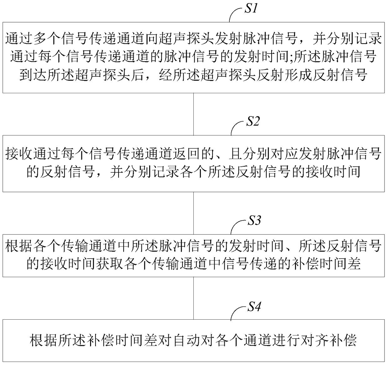
The invention provides an automatic ultrasonic probe scanning precision calibration method and system. The method comprises the steps of emitting pulse signals to an ultrasonic probe through a plurality of signal transmission channels, and recording the emission time of each pulse signal passing through the corresponding signal transmission channel; reflecting the pulse signals through the ultrasonic probe to form reflection signals after the pulse signals reach the ultrasonic probe; receiving the reflection signals which are returned through each signal transmission channel and correspond to the emitted pulse signals respectively, and recording the receiving time of each reflection signal; acquiring signal transmission compensation time difference in the transmission channels according to the emission time of the pulse signals in the transmission channels and the receiving time of the reflection signals; automatically conducting alignment compensation on the channels according to the compression time difference. By the adoption of the method and system, clinical diagnosis convenience and using efficiency of ultrasonic imaging equipment are improved, and ultrasonic diagnosis image quality is improved.

Description

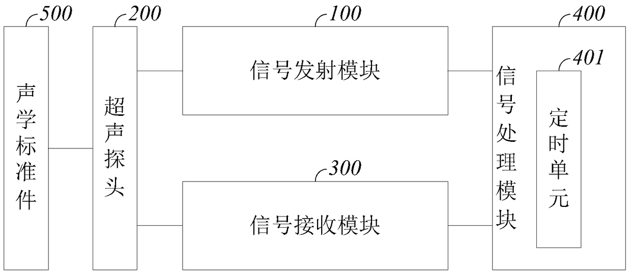
technical field [0001] The invention belongs to the field of ultrasonic diagnostic imaging, and relates to an automatic calibration method and system for the scanning accuracy of an ultrasonic probe. Background technique [0002] Ultrasound imaging equipment has become one of the most widely used clinical diagnostic tools because of its non-invasive, real-time, convenient operation, and low price. [0003] combine figure 1 as shown, figure 1 It is a basic composition block diagram of ultrasonic diagnostic equipment in the prior art. The ultrasonic imaging equipment is at least composed of an ultrasonic host and an ultrasonic probe. The ultrasonic host includes a transmitting module, a receiving module, a transmitting and receiving switch module, and a control and data processing module. 1. Host computer; the transmitting module transmits ultrasonic signals through the probe at specific time intervals; the receiving module receives echo signals through the probe and synthes...

Claims


Application Information

Patent Timeline
Patent Type & Authority Patents(China)
IPC IPC(8): A61B8/00
CPCA61B8/4444A61B8/58
Inventor 彭利军
Owner VINNO TECH (SUZHOU) CO LTD
Learn More