Surgical hemostatic forceps for general surgery department
A technique of hemostatic forceps and general surgery, applied in surgical forceps, surgery, medical science and other directions, can solve the problems of affecting the surgical effect, large clamping force, and small clamping force, etc., to improve surgical efficiency, improve hygiene, structure Solid and compact effect
- Summary
- Abstract
- Description
- Claims
- Application Information
AI Technical Summary
Problems solved by technology
Method used
Image

Examples
Embodiment 1
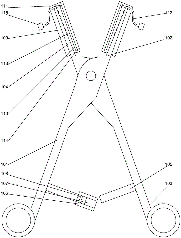
[0023] Such as figure 1 As shown, a kind of surgical hemostatic forceps for general surgery includes a left forceps handle 101, a right forceps head 102 connected with the left forceps handle 101, a right forceps handle 103, and a left forceps head 104 connected with the right forceps handle 103. The left pliers handle 101 and the right pliers handle 103 are hinged to each other through pin shafts, and locking strips 105 are respectively arranged on the opposite surfaces of the left pliers handle 101 and the right pliers handle 103, and on the The above-mentioned locking strips 105 are respectively provided with threads, and the locking strip 105 on the described left pliers handle 101 is provided with an annular groove 108, and on the locking strip 105 on the described left pliers handle 101 A fixed rod 106 is provided. The fixed rod 106 is engaged in the annular groove 108 and can rotate around the axis of the annular groove 108. When the fixed rod 106 is away from One end ...
Embodiment 2
[0026] In this embodiment, on the basis of Embodiment 1, in order to facilitate the timely suction of blood at the surgical site during the operation, and at the same time facilitate flushing, and reduce the use of special suction and flushing equipment, preferably, on the fixed sleeve 109, respectively A deflector pad 110 is provided, and a deflector hole 111 is respectively arranged on the tip of the deflector pad 110 close to the left pliers head 104 and the right pliers head 102, and on the deflector hole 111 The guide tubes 112 are respectively connected, and the guide tubes 112 are made of medical silica gel. The blood in the clamped part can be sucked through the guide tube, and the clamped part can also be flushed through the guide tube, or the guide tube on one side can be used for flushing, and the guide tube on the other side can be used for suction , help to improve surgical efficiency.
[0027] Further preferably, in order to divert the blood and facilitate the o...
PUM
 Abstract
Description
Claims
Application Information
 - R&D
- Intellectual Property
- Life Sciences
- Materials
- Tech Scout
- Unparalleled Data Quality
- Higher Quality Content
- 60% Fewer Hallucinations
Browse by: Latest US Patents, China's latest patents, Technical Efficacy Thesaurus, Application Domain, Technology Topic, Popular Technical Reports.
© 2025 PatSnap. All rights reserved.Legal|Privacy policy|Modern Slavery Act Transparency Statement|Sitemap|About US| Contact US: help@patsnap.com