Novel bone fracture plate

A bone plate, a new type of technology, applied in the direction of outer plate, internal bone synthesis, medical science, etc., can solve the problems of increasing the patient's economic burden and pain, damage to the blood supply of the fractured end, and joint dysfunction, etc., and is conducive to fracture healing and protection. The effect of blood supply and joint function protection

Inactive Publication Date: 2016-06-15
赖金平 +3
View PDF6 Cites 4 Cited by
  • Summary
  • Abstract
  • Description
  • Claims
  • Application Information

AI Technical Summary

Problems solved by technology

Because the muscles, ligaments, and periosteum are stripped during surgery, and the entire bone plate is directly pressed on the cortical bone, the surgical exposure is large, and it is easy to further damage the blood supply of the fracture end, resulting in fracture nonunion or delayed union.
Moreover, after the fracture heals, the patient needs to undergo a second operation to remove the bone plate, which increases the financial burden and pain of the patient.
At the same time, each surgical incision has the risk of adhesion of tendons and ligaments, leading to joint dysfunction

Method used


Image

  • Novel bone fracture plate
  • Novel bone fracture plate
  • Novel bone fracture plate

Examples


Embodiment 1

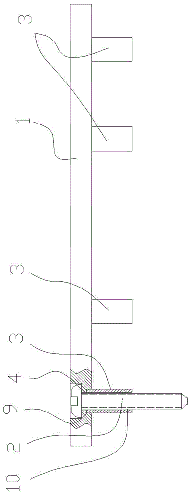
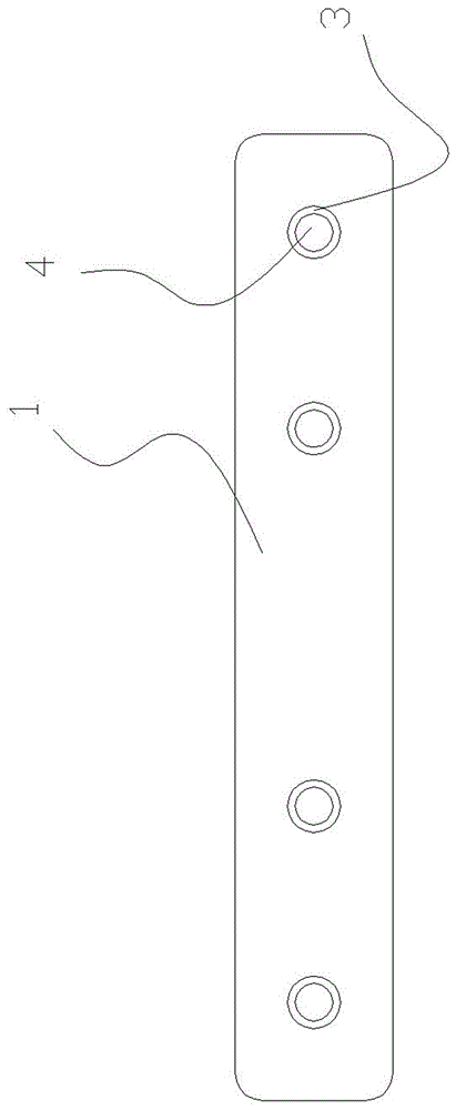
[0018] Embodiment 1: as figure 1 , 2 , 3, including bone plate body 1, screw 2, its special feature is that one side of the bone plate body 1 spans both sides of the fracture line 5, and at least two support columns 3 are set on each side (the embodiment is two support columns column), at least one support column 3 on each side is provided with a tube hole 10, the bone plate body 1 is provided with a screw hole 4, the screw hole 4 communicates with the tube hole 10 of the support column 3, and the screw 2 connects with the tube hole 10 of the bone plate body 1 The other side is inserted into the screw hole 4 and passes through the tube hole of the support column 3, and finally enters the cortical bone to complete fracture fixation.

[0019] The shape of the bone plate body 1 matches the bone or skin shape of the fracture site 5 .

[0020] The support column 3 can be fixed on the bone plate body 1 or sleeved on the screw 2 .

[0021] When the support column 3 is sleeved on t...

Embodiment 2

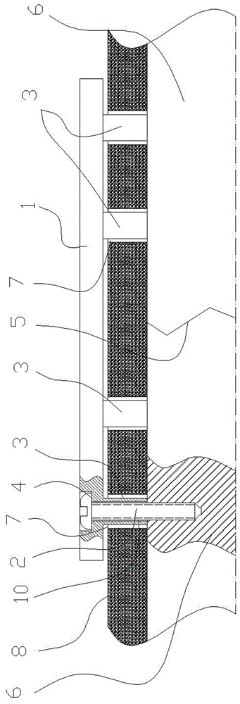
[0022] Embodiment 2: as Figure 4 As shown, this embodiment is based on Embodiment 1. Two adjacent support columns 3 are fixedly connected to the bone plate body 1 on both sides of the screw hole 4, and the screw 2 is inserted into the screw hole 4 from the other side of the bone plate body 1. Afterwards, directly enter the bone cortex to complete fracture fixation. The support column 3 may or may not have a tube hole 10. Of course, the support column 3 without the tube hole 10 can increase the contact area between the support column 3 and the bone 6. To reduce the pressure on the bones 6 per unit area.

[0023] like image 3 , 4 As shown, after the fracture is reduced, keep the fracture reduction state, select the bone plate body 1 of appropriate length, the bone plate body 1 is adapted to the bone 6 or skin at the fracture site 5 and placed outside the skin (or cut the skin to make the bone plate body 1 Body 1 is located under the skin 8), determine the entry point of scr...


PUM


Abstract

The invention relates to a novel bone fracture plate which comprises a bone fracture plate body and a screw. The novel bone fracture plate is characterized in that one of the surfaces of the bone fracture plate stretches across the two sides of a bone fracture line; at least two supporting columns are arranged on each side of one of the surfaces of the bone fracture plate; a screw hole is formed in the bone fracture plate body; the screw is inserted into the screw hole from the other side of the bone fracture plate, passes through the supporting columns and finally enters a cortical bone to complete bone fracture fixation; or the two adjacent supporting columns are fixedly connected with the bone fracture plate body on the two sides of the screw hole; the screw directly enters the cortical bone to complete bone fracture fixation after being inserted into the screw hole from the other side of the bone fracture plate body. Compared with the prior art, the novel bone fracture plate provided by the invention has the advantages that the damage caused by regular operation to blood supply for a bone fracture segment can be avoided, so that bone fracture healing is facilitated; 'inner fixation' is not needed to be taken through operation in the second-time hospitalization, so that the hospitalization expense can be effectively reduced.

Description

technical field [0001] The invention relates to an orthopedic medical instrument. Background technique [0002] Existing bone plate components generally consist of a bone plate and bone screws connected to the bone plate. During use, the skin, subcutaneous, and deep fascia are cut, the muscle layer is separated, the periosteal tissue is peeled off, the fracture segment is exposed, and the fracture is reset. Then screw the bone plate close to the cortical bone on both sides of the broken end for fixation. Because the muscles, ligaments, and periosteum are stripped during surgery, and the entire bone plate is directly pressed on the cortical bone, the surgical exposure is large, and it is easy to further damage the blood supply of the fracture end, resulting in nonunion or delayed union of the fracture. Moreover, after the fracture has healed, the patient needs to undergo a second operation to remove the bone plate, which increases the financial burden and pain of the patient...

Claims


Application Information

Patent Timeline
Patent Type & Authority Applications(China)
IPC IPC(8): A61B17/80A61B17/86
CPCA61B17/8057A61B17/86A61B2017/564
Inventor 赖金平徐志强刘礼初刘效仿
Owner 赖金平
Why Eureka
Try Eureka