
cable welding wire

A cable-type welding wire and welding wire technology, applied in welding medium, welding equipment, welding/cutting medium/material, etc., can solve the problems of poor production quality and welding performance of cable-type welding wire

Active Publication Date: 2017-11-14
SUZHOU YINLI WELDING IND TECH CO LTD
View PDF13 Cites 3 Cited by
  • Summary
  • Abstract
  • Description
  • Claims
  • Application Information

AI Technical Summary

Problems solved by technology

[0006] Therefore, the technical problem to be solved by the present invention is to overcome the defects of poor production quality and welding performance of cable welding wire in the prior art

Method used

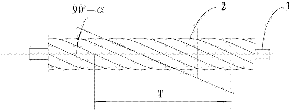
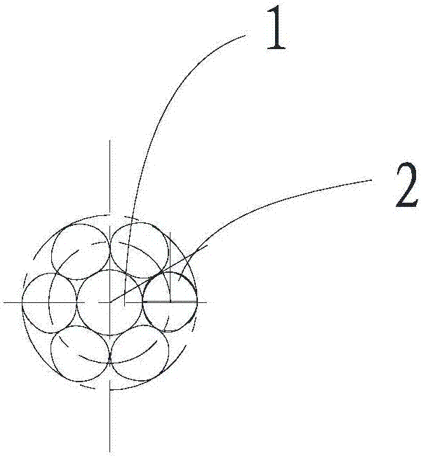
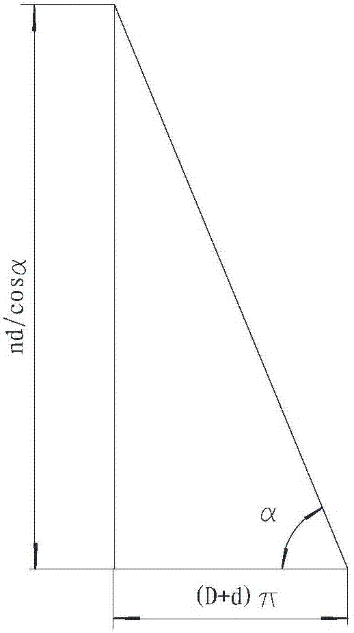

Image

  • cable welding wire
  • cable welding wire
  • cable welding wire

Examples


Embodiment 1

[0042] The structure of the cable type welding wire provided in this embodiment is 1+6, such as figure 1 and figure 2 As shown, that is, the number of peripheral welding wires is 6, and the peripheral welding wires are solid welding wires, K=1, then T=md (m=20-25, helix angle α=72.5°~76.1°). At the same time, the diameter d of the peripheral welding wire is equal to 1.6mm, and the diameter of the cable-type welding wire is about 5mm, so the optional range of lay length T is 32-40mm, and the optimum lay length (ie when m=24) = 38mm.

Embodiment 2

[0052] The structure of the cable type welding wire provided in this embodiment is 1+7, such as Figure 4 As shown, that is, the number of peripheral welding wires is 7, and the peripheral welding wires are solid welding wires, K=1, then T=md, (m=20-25, helix angle α=69.5°~73.7°). At the same time, the diameter of the peripheral welding wire is 1.85mm, the diameter of the central welding wire is 2.3mm, and the diameter of the cable welding wire is about 6mm, so the optional range of twist length is 37-46.25mm, and the best twist length (ie when m=24) = 44.4 mm. And when the welding wire feeding speed is 44.4mm / sec, the rotation frequency of the arc is 1 Hz.

Embodiment 3

[0054] The structure of the cable type welding wire provided in this embodiment is 1+8, such as Figure 5 As shown, the number of peripheral welding wires is 8, and the peripheral welding wires are solid welding wires, K=1, T=md (m=20-25, helix angle α=α=66.4°~71.3°). At the same time, when the diameter of the peripheral welding wire is 1.73mm, the diameter of the central welding wire is 2.54mm, and the diameter of the cable-type welding wire is about 6mm, then the optional range of lay length: 34.6-43.25mm, the best lay length (ie when m=24) = 41.5mm. And when the welding wire feeding speed is 41.5 mm / s, the rotation frequency of the arc is 1 Hz.


PUM


Abstract

The invention provides a cable type welding wire. The cable type welding wire comprises a center welding wire and n peripheral welding wires arranged around the center welding wire in a spiral rotating manner, wherein the diameter of each of the peripheral welding wires is d, and the neighboring peripheral welding wires are separately arranged in an intersecting manner. The cable type welding wire is characterized in that the lay length T of each of the peripheral welding wires is equal to K*m*d, wherein K is the structure factor of the peripheral welding wires, m is the lay length multiple, and d is the diameter of each of the peripheral welding wires; K is larger than or equal to 1, and less than or equal to 1.5; m is larger than or equal to 20, and less than or equal to 25. According to the cable type welding wire provided by the invention, wire breakage is not liable to generate in the manufacturing process; during welding, the peripheral welding wires are arranged compactly, so that the wire feeding process is more stable, and the welding performance of the cable type welding wire is improved.

Description

technical field [0001] The invention relates to the field of welding wire technology, in particular to a cable type welding wire. Background technique [0002] Cable-type welding wire (also known as multi-strand welding wire) is composed of a central welding wire and a plurality of peripheral welding wires that are tangent to each other and have the same diameter and are wound on the central welding wire at a helix angle α. The cable-type welding wire has the advantages of good coiling, good rigidity when feeding the wire, wide penetration and high deposition efficiency during welding, and the reasons are: (1) welding with cable-type welding wire (such as CO 2 During gas shielded welding), the small anode area of ​​the peripheral welding wire rotates around the anode area of ​​the central welding wire with the feeding of the cable type welding wire, and quickly synthesizes into a unified beam-shaped rotating arc column area. The beam-shaped rotating arc is conducive to the m...

Claims


Application Information

Patent Timeline
Patent Type & Authority Patents(China)
IPC IPC(8): B23K35/02
CPCB23K35/02
Inventor 时振时山奇
Owner SUZHOU YINLI WELDING IND TECH CO LTD
Learn More