Warp strand unbinding device

A warp and untwisting technology, which is applied in the direction of twisting, auxiliary equipment for weaving, textiles, etc., can solve the problems of high working intensity and low efficiency, and achieve the effects of convenient installation and debugging, improving work efficiency and saving manpower

Active Publication Date: 2016-06-15
YONGXUSHENG MACHINERY TECH CHANGZHOU CO LTD
View PDF5 Cites 2 Cited by
  • Summary
  • Abstract
  • Description
  • Claims
  • Application Information

AI Technical Summary

Problems solved by technology

At present, most of them use manual untwisting, which has high working intensity and low efficiency. Therefore, an automatic untwisting device is urgently needed to change the current status quo.

Method used


Image

  • Warp strand unbinding device
  • Warp strand unbinding device
  • Warp strand unbinding device

Examples


Embodiment 1

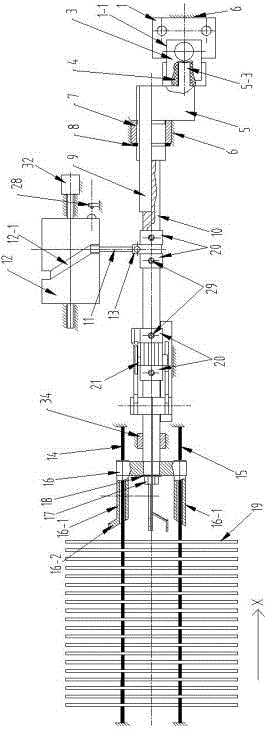
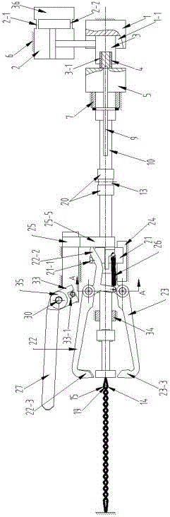
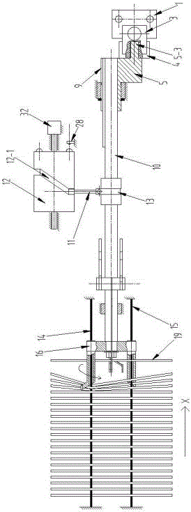
[0044] Embodiment 1: see attached figure 1 ~ attached Figure 14 , a warp yarn untwisting device, comprising a swing driving mechanism, a moving driving mechanism, an executing mechanism, a warp yarn isolating mechanism, and a warp yarn isolating and debugging mechanism.

[0045] The swing drive mechanism includes a cylinder 2 fixed to the frame 6 of the threading machine, a bracket 1 fixed to the frame 6 of the threading machine, a slider 3, and an eccentric shaft 5 movably connected to the frame 6 of the threading machine through a rear sliding bearing 7 , the left side of the rear sliding bearing 7 is provided with a retaining ring 8 for its axial limit, a bracket chute 1-1 is provided on the bracket 1, the cylinder 2 is opposite to the notch of the bracket chute 1-1, and the slider 3 Movably fit in the bracket chute 1-1, a slider groove 3-1 perpendicular to the bracket chute 1-1 is provided on the side of one end of the slider 3, and a spacer is movably fitted in the slid...


PUM


Abstract

The invention relates to a warp strand unbinding device. The device comprises a swing driving mechanism, a movement driving mechanism, an actuation mechanism and a warp isolation mechanism. The swing driving mechanism comprises a cylinder, a support, a sliding block connected with a piston rod of the cylinder and arranged in a support groove in a matched mode and an eccentric shaft. The eccentric end of the eccentric shaft is connected with a cushion block in a sliding block groove. One end of a deflector rod of the movement driving mechanism is arranged in a cylindrical surface cam spiral groove in a matched mode. The actuation mechanism comprises a rotary shaft rotationally connected to a drawing-in machine frame and a U-shaped fork arm fixed to one end of the rotary shaft. The other end of the rotary shaft is connected to the rotation center of the eccentric shaft in a matched mode. The other end of the deflector rod is connected with a lantern ring of the rotary shaft. An upper twisted rope and a lower twisted rope penetrate through two end arms of the fork arm respectively. Two lugs of the warp isolation mechanism make contact with the bevel edges of two arm holding levers. Two suspended edges of the two-arm support are connected with the two arm holding levers through tension springs respectively. Through the warp strand unbinding device, warp stranded by the two twisted ropes can be unbound piece by piece automatically and quickly, installation and debugging are convenient, manpower is saved, work efficiency is improved, and cost is low.

Description

technical field [0001] The invention relates to a warp untwisting device, which is used for an automatic drawing-in machine. Background technique [0002] With the development of science, automation technology has penetrated into all fields of weaving industry. As an automatic threading machine that integrates machine, electricity, light and gas control, it has begun to enter some high-quality enterprises. Its threading efficiency is more than 10 times that of manual threading, and its quality and reliability are better than manual operation. [0003] After being sized and dried by the sizing machine, the warp yarns are usually glued together with the sizing material. In order to keep the warp yarns from being arranged in disorder, two upper and lower twisted ropes are generally used to thread between the warp yarns on the weaving shaft in an orderly manner. The warp yarns that stick together are separated one by one, and the path of the upper skein rope to wind the warp ya...

Claims


Application Information

Patent Timeline
Patent Type & Authority Applications(China)
IPC IPC(8): D02H9/02D03J1/14
CPCD02H9/02D03J1/14
Inventor 刘进球余涛刘薇
Owner YONGXUSHENG MACHINERY TECH CHANGZHOU CO LTD
Why Eureka
Try Eureka