
A bridge widening structure with a steel cap beam added to the top of the pier

A technology of steel cap girders and bridges, which is applied in the direction of erection/assembly of bridges, bridges, bridge maintenance, etc. It can solve the problems of interrupting traffic on the bridge, limited design load of widening, and impact of bridge piers on ground traffic, etc., to achieve ground traffic impact Small size, short construction period, and little impact

Inactive Publication Date: 2017-10-13
DALIAN UNIV OF TECH
View PDF6 Cites 0 Cited by
  • Summary
  • Abstract
  • Description
  • Claims
  • Application Information

AI Technical Summary

Problems solved by technology

[0006] In order to solve the problems existing in the existing old bridge widening technology, such as limited widening design load, new bridge piers affecting ground traffic, and interruption of bridge traffic during construction, the present invention provides a new old bridge widening technology. The structure does not need to add new piers, the widening design load is not limited, and the construction process does not need to interrupt the traffic on the bridge

Method used


Image

  • A bridge widening structure with a steel cap beam added to the top of the pier
  • A bridge widening structure with a steel cap beam added to the top of the pier
  • A bridge widening structure with a steel cap beam added to the top of the pier

Examples


Embodiment Construction

[0014] The specific embodiments of the present invention will be described in detail below in conjunction with the technical solutions and accompanying drawings.

[0015] The original bridge width is 18.5 meters, the main girder is a concrete box girder section, and the bridge width after widening is 26m. The specific construction process is as follows:

[0016] (1) Steel components such as steel cover beams and steel box girders on both sides are prefabricated in the factory.

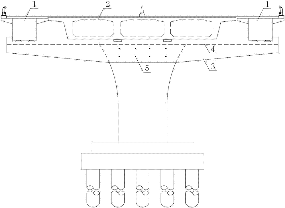
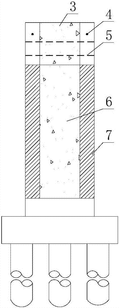
[0017] (2) Chisel the original pier, plant reinforcement, pour concrete after pouring, thicken the longitudinal bridge of the pier by 0.5 meters, install the pre-buried section of the steel cover beam on the top of the thickened concrete layer, and tension and fix the pre-buried section of the steel cover beam. Stress anchor bars fix the steel cover beams and splice the remaining steel cover beams.

[0018] (3) Control the traffic on the bridge, remove the original bridge anti-collision guardrail and ...


PUM


Abstract

The invention provides a structure for broadening a bridge by additionally arranging a steel cap beam on the top of a pier, belonging to the technical field of bridge engineering. According to the structure for broadening the bridge by additionally arranging the steel cap beam on the top of the pier, post-pouring concrete is poured at the two sides of the original concrete pier, and the specific concrete width of the post-pouring concrete is determined according to the stress of the upper part of the bridge; the steel cap beam is additionally arranged on the top of the pier poured with the post-pouring concrete; the steel cap beam has a box cross section and is formed by steel plates in a welding way; according to the stress of the upper part of the bridge, prestressed steel beams and prestressed anchor bars are arranged in the steel cap beam; the prestressed steel beams are vertical to the prestressed anchor bars in the steel cap beam; steel box beams are additionally arranged at the two sides of an original concrete box beam; the steel box beams are positioned on the steel cap beam. The structure for broadening the bridge by additionally arranging the steel cap beam on the top of the pier has the effects and advantages that the structure of the original bridge main body is not torn down, so that the economy of widening reformation is guaranteed; the design load of the structure of the newly added steel box beams is not limited, so that the operation reliability of the broadened bridge is high; in the construction process, the traffic on the bridge is not needed to be interrupted; furthermore, the structure for broadening the bridge by additionally arranging the steel cap beam on the top of the pier is short in site construction period and has little influence on ground transportation.

Description

technical field [0001] The invention belongs to the technical field of bridge engineering, relates to bridges that need to be widened and reconstructed in bridge engineering, especially urban bridges that need to be widened on both sides, and specifically provides a bridge widening structure with steel cap beams added on top of piers. Background technique [0002] At present, the usual practices in the field of bridge widening include the following: [0003] Increase reinforced concrete cantilever beams: remove old bridge railings and sidewalk facilities, increase or increase cantilever beams to achieve the purpose of widening the bridge. This method is suitable for double-sided widening of general beam bridges and arch bridges. However, due to the limitation of its own bearing capacity, the widening span is limited, and the load acting on the cantilever should not be too large. It is usually only suitable for pedestrians and not for vehicles. [0004] Adding side beams: Fo...

Claims


Application Information

Patent Timeline
Patent Type & Authority Patents(China)
IPC IPC(8): E01D22/00
CPCE01D22/00
Inventor 李文武祁伟超王骞张哲
Owner DALIAN UNIV OF TECH
Learn More