A mechanism capable of continuously changing valve lift

A valve lift and continuous technology, applied in mechanical equipment, engine components, machines/engines, etc., can solve problems such as poor fuel economy and emission improvement, complicated control methods, and stiff driving experience, etc., to achieve improved combustion Efficiency and fuel economy, simple and fast control, smooth adjustment process effect

Active Publication Date: 2018-04-20
HANGZHOU XZB TECH
View PDF6 Cites 0 Cited by
  • Summary
  • Abstract
  • Description
  • Claims
  • Application Information

AI Technical Summary

Problems solved by technology

The segmented variable valve lift mechanism can only change the value of the valve lift in two to three stages due to the mechanical structure, and the segmented variable valve lift mechanism is between two adjacent stages. The driving experience is blunt and incoherent, and the working conditions of the internal combustion engine cannot be adjusted for all working conditions, so the improvement of fuel economy and emissions is not good.
[0004] However, the continuous variable valve lift mechanism that has been mass-produced and installed in the market is relatively complicated in structure, resulting in high cost, large mechanism, need to change the design of the entire engine cylinder head, prone to failure, and improved fuel economy. Energy consumption is instead consumed by friction between complex mechanical structures and other disadvantages
[0005] In addition, some valve lift adjustment mechanisms on the market use hydraulic or complex mechanical mechanisms to adjust
The control method is complex and the control speed is slow

Method used


Image

  • A mechanism capable of continuously changing valve lift
  • A mechanism capable of continuously changing valve lift
  • A mechanism capable of continuously changing valve lift

Examples


Embodiment approach 1

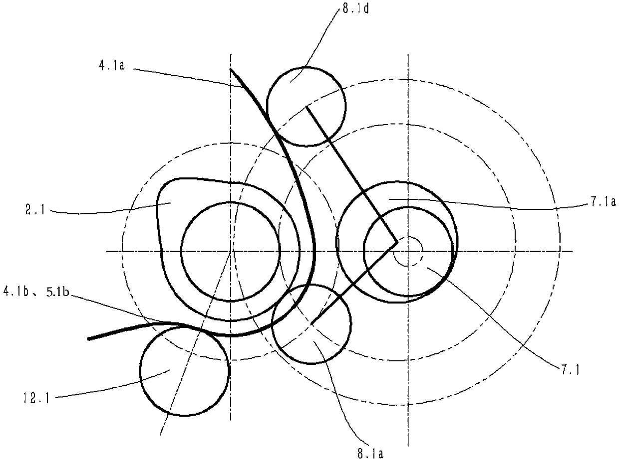
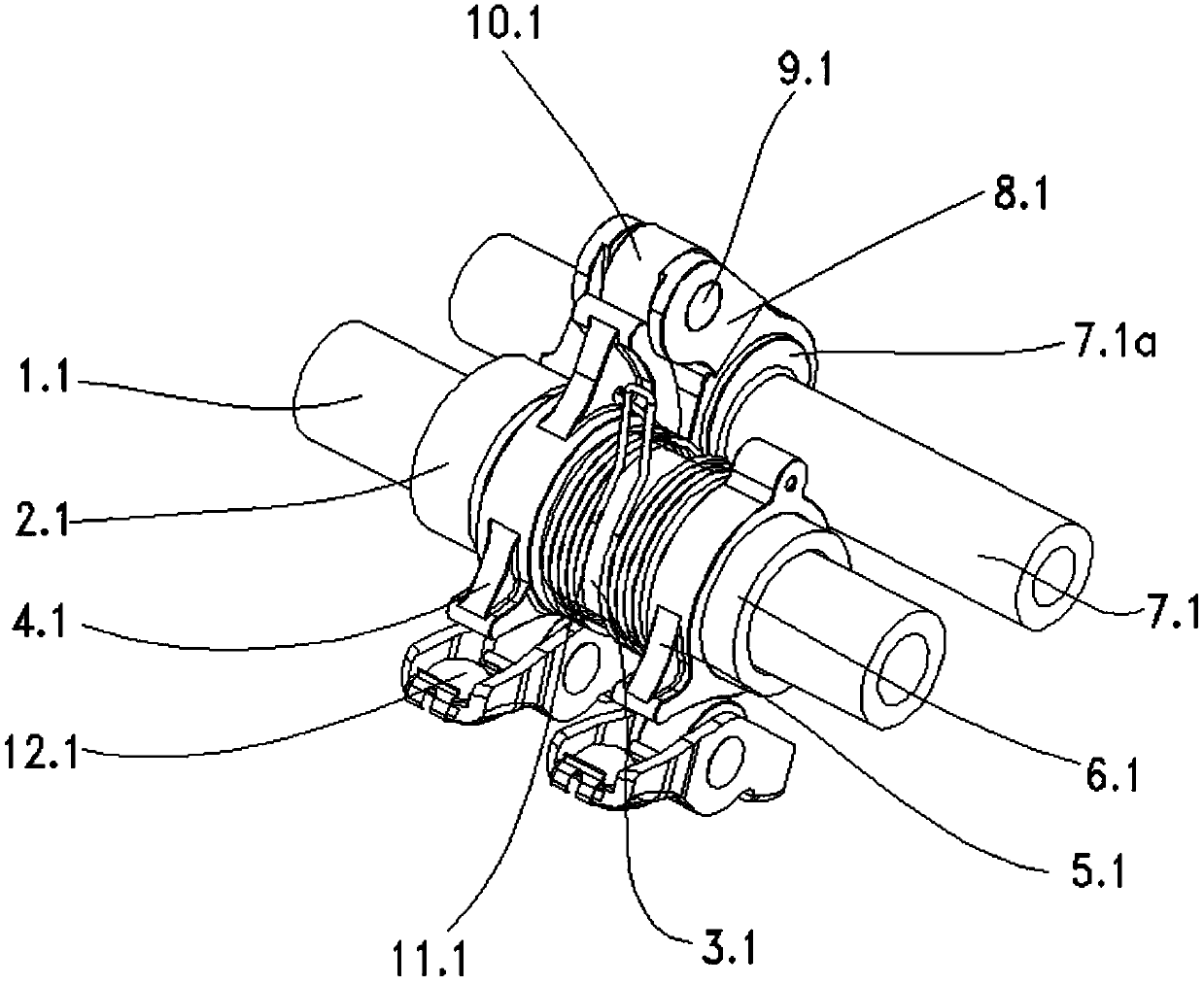
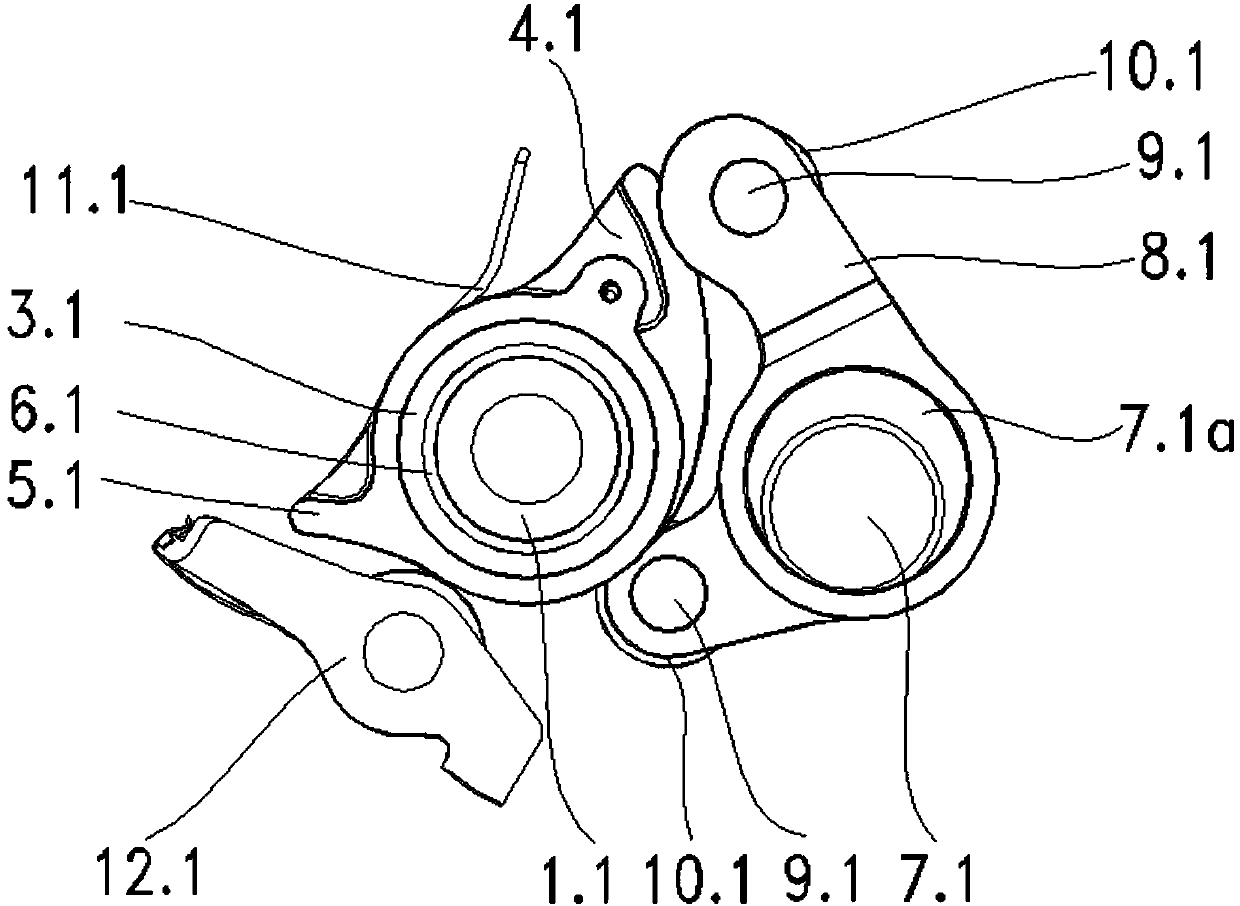
[0057] Implementation mode one: if Figure 2-15 As shown, a mechanism that can continuously change the valve lift includes camshaft I1.1, cam I2.1, control shaft I7.1 and rocker arm I12.1, and camshaft I1.1 is located on cam I2.1- The side empty sleeve has a swing camshaft 3.1, the main swing cam 4.1 and the auxiliary swing cam 5.1 are arranged on the swing camshaft 3.1, the main swing cam 4.1 is provided with a main input end 4.1a and a main output end 4.1b, and the auxiliary swing cam 5.1 The auxiliary output end 5.1b is set at the same horizontal position as the main output end 4.1b; the eccentric shaft section I7.1a is set on the control shaft I7.1, and the control arm I8.1 and the control arm I8.1 are set on the eccentric shaft section I7.1a. 1 is provided with an input rod I 8.1a and an output rod I 8.1d; the outer end of the input rod I 8.1a of the cam I 2.1 and the control arm I 8.1 is offset, and the outer end of the output rod I 8.1d is in contact with the main swing...

Embodiment approach 2

[0064] Implementation mode two: if Figure 17-33 As shown, a mechanism that can continuously change the valve lift includes camshaft II 1.2, cam II 2.2, control shaft II 6.2 and rocker arm II 15.2, and two swing cams 3.2 are centered on cam II 2.2 It is left-right symmetrical and arranged on the camshaft II1.2 in the form of clearance fit. The swing cam 3.2 is provided with an input end 3.2a and an output end 3.2b; an eccentric shaft section II6.2a is set on the control shaft II6. Ⅱ6.2a is provided with a control arm Ⅱ7.2, and the control arm Ⅱ7.2 is provided with an input rod Ⅱ7.2a and two output rods Ⅱ7.2b; the cam Ⅱ2.2 and the input rod Ⅱ7.2a of the control arm Ⅱ7.2 The outer ends offset each other, the outer ends of the two output rods II 7.2b offset the input ends 3.2a of the two swing cams 3.2 respectively, and the two output ends 3.2b offset the two rocker arms II 15.2 respectively.

[0065] combine Figure 22 , Figure 25 and Figure 31-33 As shown, the input ends ...


PUM


Abstract

The invention discloses a mechanism capable of continuously changing valve lift. The mechanism comprises a cam shaft and a rocker arm in a cylinder cover, wherein a cam and a swing cam are arranged on the cam shaft; an input end and an output end are arranged on the swing cam; a control shaft is parallel to the cam shaft; an eccentric shaft section is arranged on the control shaft; a control arm is arranged at the eccentric shaft section; an input rod and an output rod are arranged on the control arm; the input rod is placed against the cam; and the output rod is placed against the input end of the swing cam while the output end is placed against the rocker arm. The mechanism disclosed by the invention has the advantages of simple structure, small number of parts, low cost, compact assembly and low occupation of engine space; most of the parts are standard parts and symmetric parts which are relatively convenient to process and assemble; and moreover, the valve lift can be continuously changed in the range, the adjusting range is large, the adjusting process is smooth, the combustion efficiency and fuel economy of an internal combustion engine can be remarkably increased, the emission behavior is improved, the control is easy and quick, and the adjustment of the valve lift of the engine can be finished simply by adjusting the rotation angle of the control shaft.

Description

technical field [0001] The invention relates to the technical field of engine equipment, in particular to a mechanism capable of continuously changing valve lift. Background technique [0002] With the development of the automobile industry, people have higher and higher requirements on engine performance, fuel consumption and emission. Variable valve lift technology has become one of Peugeot's key technologies to measure engine performance. The variable valve lift technology has changed the traditional engine valve lift fixed state, providing the best valve lift within the range of engine operating conditions, so that the engine can obtain the required valve lift in both high-speed and low-speed areas , so as to improve the high-speed power and low-speed torque of the engine, better solve the contradiction between high-speed and low-speed, high-load and small-load power and economy, and improve exhaust emissions at the same time. [0003] Therefore, variable valve lift tec...

Claims


Application Information

Patent Timeline
Patent Type & Authority Patents(China)
IPC IPC(8): F01L13/00
CPCF01L13/0026
Inventor 徐纳任海军
Owner HANGZHOU XZB TECH
Why Eureka
Try Eureka