Laser emitting apparatus

A laser emission and laser technology, used in measuring devices, instruments, mapping and navigation, etc., can solve problems such as reduced work efficiency, non-parallel, and inability to guarantee accuracy.

Inactive Publication Date: 2016-06-15
NANJING CHERVON IND
View PDF14 Cites 12 Cited by
  • Summary
  • Abstract
  • Description
  • Claims
  • Application Information

AI Technical Summary

Problems solved by technology

But usually because the working surface is not necessarily parallel to the horizontal plane, the projected line emitted by the laser line projector is often not parallel to the horizontal plane. In order to solve this problem, the existing laser line projector usually needs an auxiliary adjustment Flat device, which will inevitably i

Method used


Image

  • Laser emitting apparatus
  • Laser emitting apparatus
  • Laser emitting apparatus

Examples


Embodiment Construction

[0052] The present invention will be specifically introduced below in conjunction with the accompanying drawings and specific embodiments.

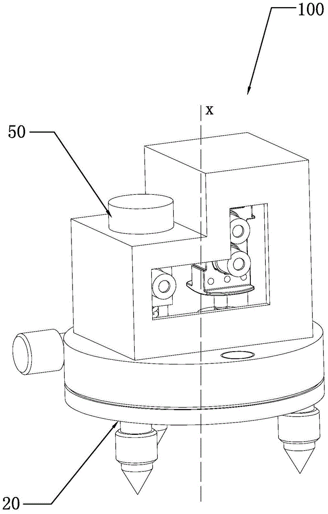
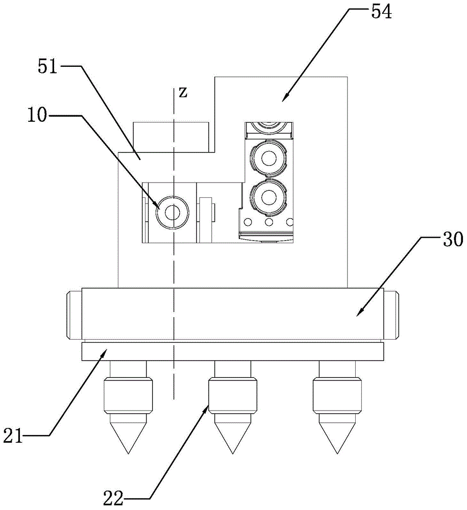
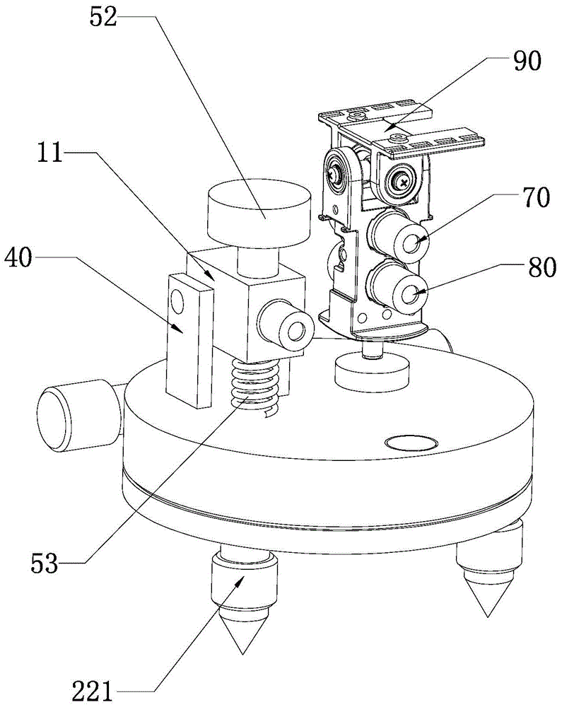
[0053] The present invention proposes a laser emitting device, which can emit a high-precision horizontal projection line L1 parallel to the horizontal plane through adjustment, and can also adjust the height of the horizontal projection line L1 as required.

[0054] Figure 1 to Figure 5 Shown is the structure of the first embodiment of the laser emitting device 100 of the present invention, please refer to Figure 1 to Figure 5 , the laser emitting device 100 of the present invention at least includes: a first light source assembly 10 , a support assembly 20 , a rotating disk 30 , a connection assembly 40 , a height adjustment assembly 50 and a fine adjustment assembly 60 .

[0055] The first light source assembly 10 can emit a laser surface covering a first preset angle range, that is to say, the laser surface presents an angle shape,...


PUM


Abstract

The present invention discloses a laser emitting apparatus comprising a first light source assembly, a support assembly, a rotating disk and a height adjusting component, the first light source assembly is capable of emitting a laser surface covering a first predetermined angle range, the support assembly comprises a base and an adjusting assembly, the adjusting assembly is used for adjustment of the position of a base, the rotating disk can rotate relative to the base around a first axis, the height adjusting component can be used for adjustment of an included angle between the laser surface of the first light source assembly and the first axis, and the f the first light source assembly can rotate relative to the rotating disk around a second axis as a shaft. The laser emitting apparatus can project high-level-degree projecting lines with different heights.

Description

technical field [0001] The invention relates to a laser device, in particular to a laser emitting device. Background technique [0002] The laser line projector is a laser beam that emits a laser beam that propagates along a straight line through a laser source. The laser beam diffuses through a cylindrical mirror to form a laser surface with a certain diffusion angle. When the laser surface is projected on the wall , that is, a projection line extending in a straight line can be formed on the wall. But usually because the working surface is not necessarily parallel to the horizontal plane, the projected line emitted by the laser line projector is often not parallel to the horizontal plane. In order to solve this problem, the existing laser line projector usually needs an auxiliary adjustment Flat device, this will inevitably increase the complexity of the operation, and the accuracy cannot be guaranteed. Furthermore, when multiple horizontal lines need to be emitted, the ...

Claims


Application Information

Patent Timeline
IPC IPC(8): G01C15/00
Inventor 吴兵
Owner NANJING CHERVON IND
Why Eureka
Try Eureka