
Device and method for measuring modulation transfer function of optical lens based on infinite conjugate optical path

A modulation transfer function and optical lens technology, which is used in measuring devices, testing optical performance, optical instrument testing, etc., can solve problems such as large errors, poor stability, slow speed, etc. Effect

Active Publication Date: 2016-06-15
上海信智精密光学有限公司
View PDF10 Cites 33 Cited by
  • Summary
  • Abstract
  • Description
  • Claims
  • Application Information

AI Technical Summary

Problems solved by technology

[0006] The purpose of the present invention is to provide a device and method for measuring the modulation transfer function of the optical lens based on the infinite conjugate optical path of the slit target in order to overcome the above-mentioned defects in the prior art. The device and method of the present invention can be used to measure the focal length range of The modulation transfer function of the 1-12mm optical lens solves the problems of large error, slow speed and poor stability in the testing process of the optical lens modulation transfer function in the background technology

Method used


Image

  • Device and method for measuring modulation transfer function of optical lens based on infinite conjugate optical path
  • Device and method for measuring modulation transfer function of optical lens based on infinite conjugate optical path
  • Device and method for measuring modulation transfer function of optical lens based on infinite conjugate optical path

Examples


Embodiment 1

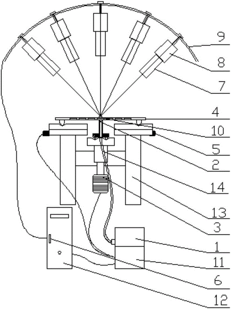
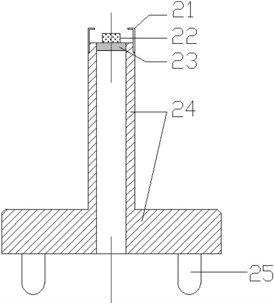
[0057] A device for measuring the modulation transfer function of an optical lens with an infinite conjugate optical path, such as figure 1 As shown, it includes a main frame 13, a one-dimensional focusing motor 3, a lens tray 4, a motor controller 11, an umbrella frame 9, an LED light source 1 and a computer 12, and the main frame 13 is used to support a two-dimensional motion platform 5 and a slit The target 2; the one-dimensional focusing motor 3 is connected under the slit target 2, and drives the slit target 2 to move in the vertical direction; the lens tray 4 is arranged on the two-dimensional motion platform 5, driven by the two-dimensional motion platform 5 Moving in the horizontal direction, it is used to place the lens 10 to be tested; the motor controller 11 is connected with the one-dimensional focusing motor 3 and the two-dimensional moving platform 5, and controls the motion of the one-dimensional focusing motor 3 and the two-dimensional moving platform 5; The um...


PUM


Abstract

The invention relates to a device and method for measuring a modulation transfer function of an optical lens based on an infinite conjugate optical path. The method comprises the following steps: installing a slit target; enabling a to-be-measured lens to be placed in a lens pallet, and placing the lens pallet on a two-dimensional platform; turning on an LED light source, so as to provide illumination for a testing system; searching an optimal focal plane of the to-be-measured lens, and determining the accurate placement position of a slit; adjusting the specific position of an image collection unit, and obtaining the optimal photographing azimuth of a slit image; photographing the tilt image through the to-be-measured lens, and transmitting the slit image to a computer; processing the slit image and obtaining an MTF curve of the to-be-measured lens; precisely controlling the position of the tilt target and the position of the lens pallet through a motor controller, and achieving the continuous online testing of an MTF value of the to-be-measured lens on the computer platform. The method and device can be used for measuring the lens with a big field angle, and solve problems that a conventional infinite conjugate optical system and a conventional edge method are large in optical lens error and poor in stability.

Description

technical field [0001] The invention relates to a method and a device for measuring a modulation transfer function, in particular to a device and a method for measuring the modulation transfer function of an optical lens based on an infinite conjugate optical path of a slit target. Background technique [0002] Modulation transfer function (MTF) is an accurate, objective and quantitative image quality evaluation index for optical lenses, and is recognized as the most effective and comprehensive imaging quality evaluation method for optical lenses. If the object is regarded as composed of frequency spectrums of various frequencies, MTF reflects the ability of the optical system to transmit different frequency components of the object. Generally speaking, the high-frequency part reflects the detail transfer ability of the object, the mid-frequency part reflects the layer transfer of the object, and the low-frequency part reflects the outline transfer of the object. At present...

Claims


Application Information

Patent Timeline
IPC IPC(8): G01M11/02
CPCG01M11/0207
Inventor 白学坤庄怀港谭羽
Owner 上海信智精密光学有限公司
Learn More