Super-high-temperature electromagnetic acoustic sensor and obtaining method thereof

An electromagnetic ultrasonic and acquisition method technology, which is applied in the direction of material analysis, instruments, and scientific instruments using sound waves/ultrasonic waves/infrasonic waves, and can solve problems such as difficult to detect high-temperature equipment

Inactive Publication Date: 2016-06-15
CHINA SPECIAL EQUIP INSPECTION & RES INST
View PDF6 Cites 16 Cited by
  • Summary
  • Abstract
  • Description
  • Claims
  • Application Information

AI Technical Summary

Problems solved by technology

[0006] The main purpose of the present invention is to provide an ultra-high temperature electromagnetic ultrasonic sensor and its acquisition method to solve the problem that the electromagnetic ultrasonic sensor in the prior art is difficult to detect high temperature equipment

Method used


Image

  • Super-high-temperature electromagnetic acoustic sensor and obtaining method thereof
  • Super-high-temperature electromagnetic acoustic sensor and obtaining method thereof
  • Super-high-temperature electromagnetic acoustic sensor and obtaining method thereof

Examples


Embodiment 1

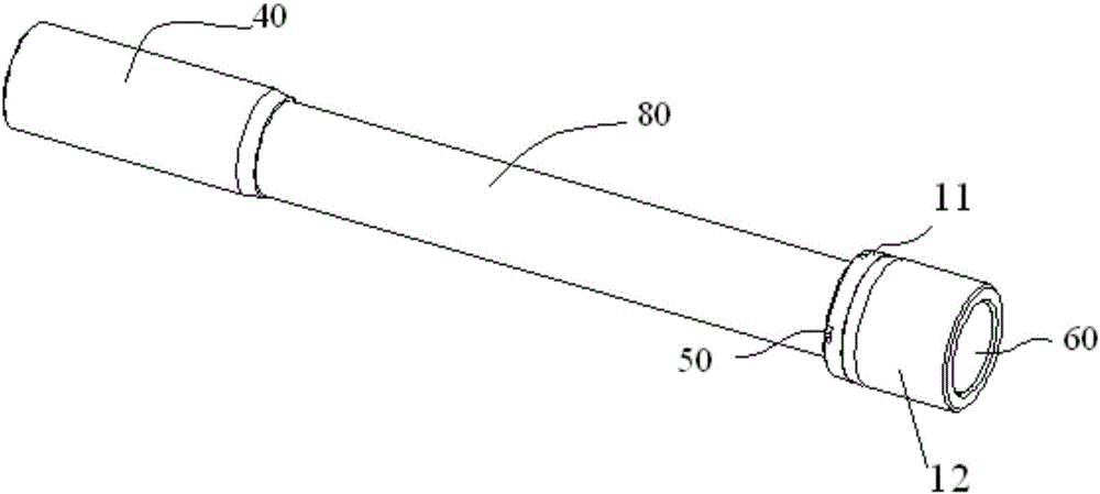
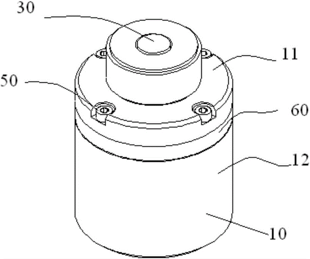
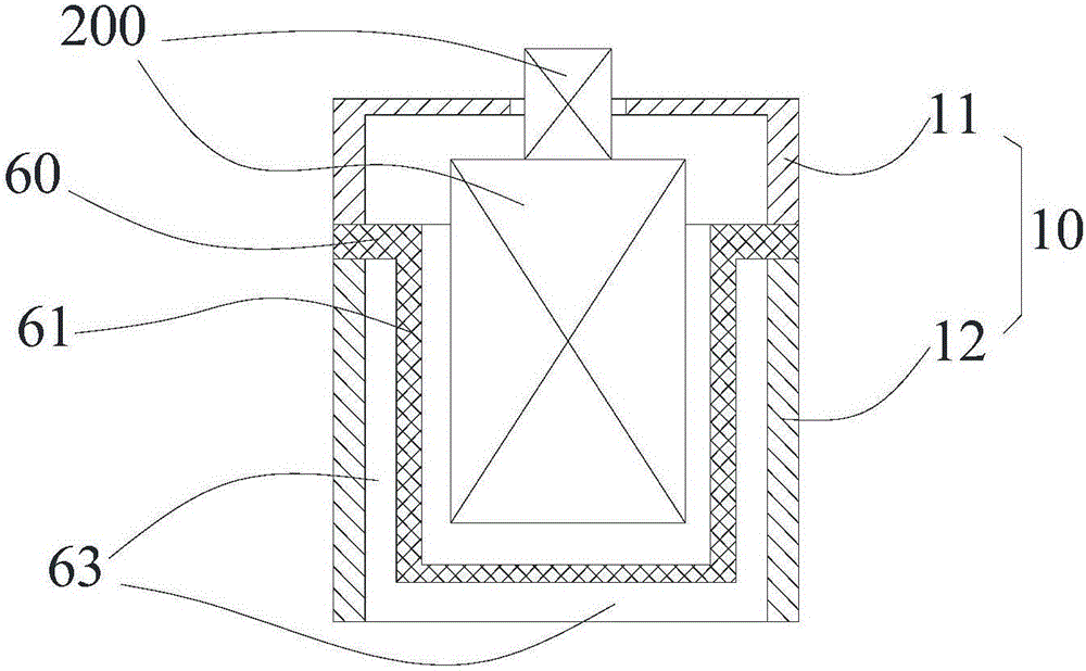
[0035] Such as Figure 1 to Figure 4 As shown, in Embodiment 1 of the present invention, the ultra-high temperature electromagnetic ultrasonic sensor includes a housing 10 , a sensor assembly 200 and a heat insulation structure 60 . The sensor assembly 200 includes a magnet and coil assembly 20 and a signal connector 30 . The magnet and coil assembly 20 is arranged inside the housing 10; the signal connector 30 is connected to the coil connector of the magnet and coil assembly 20; the heat insulation structure 60 is arranged inside the housing 10 and is located between the housing 10 and the magnet and coil assembly 20 between.

[0036] Through the above settings, the heat insulation structure 60 can delay the heat conduction of the high-temperature equipment to the inside of the housing 10 for a certain period of time, thereby protecting the sensor components 200 such as the magnet and the coil component 20 inside the housing 10 from being damaged by high temperature. When ...

Embodiment 2

[0099] In the second embodiment of the present invention, the difference between the second embodiment and the first embodiment is that the heat insulation structure 60 is one or more layers of heat insulation pads arranged on the side of the casing 10 facing the device under test. The heat insulation pad is fixedly connected with the housing 10 . This heat insulation pad is made of high temperature resistant material. The shape of the heat insulation pad is adapted to the inner shape of the casing 10 .

[0100] From the above description, it can be seen that the above-mentioned embodiments of the present invention have achieved the following technical effects: the heat insulation structure can delay the heat conduction of the high-temperature equipment to the inside of the housing for a certain period of time, thereby protecting the magnets and Coil components and other components are protected from high temperature damage, so that when the ultra-high temperature electromagn...


PUM

PropertyMeasurementUnit
heightaaaaaaaaaa
sizeaaaaaaaaaa
sizeaaaaaaaaaa

Abstract

The invention provides an ultra-high temperature electromagnetic ultrasonic sensor and an acquisition method thereof. The ultra-high temperature electromagnetic ultrasonic sensor includes: a housing; a sensor assembly arranged inside the housing; a heat insulation structure arranged inside the housing and between the housing and the sensor assembly; where the ultra-high temperature electromagnetic ultrasonic sensor refers to An electromagnetic ultrasonic sensor capable of detecting equipment to be inspected with a temperature less than or equal to 750°C. Due to the heat insulation structure between the sensor assembly and the housing, when the ultra-high temperature electromagnetic ultrasonic sensor is used to detect high-temperature equipment, the heat insulation structure can delay the heat conduction of the high-temperature equipment to the inside of the housing for a certain period of time, thereby protecting Sensor components such as magnets and coils located inside the casing are protected from high temperature damage, so the function of detecting equipment to be inspected with high temperature can be realized.

Description

technical field [0001] The invention relates to the technical field of ultrasonic nondestructive testing, in particular to an ultra-high temperature electromagnetic ultrasonic sensor and an acquisition method thereof. Background technique [0002] Equipment used in petroleum, chemical, natural gas, nuclear power and other industrial production, such as pipelines, pressure vessels, etc., often work in high temperature and high pressure environments. How to ensure the safe and reliable long-term operation of the above-mentioned equipment is of great significance. Recently, as the number of accidents caused by the failure of the above-mentioned in-service equipment is increasing year by year, there is an urgent need for accurate and reliable quality inspection of high-temperature in-service equipment. [0003] At present, the non-destructive testing technologies applied under high temperature conditions include infrared thermal imaging technology, ultrasonic testing technology...

Claims


Application Information

Patent Timeline
Patent Type & Authority Applications(China)
IPC IPC(8): G01N29/24
CPCG01N29/2412
Inventor 郑阳郑晖张宗健谭继东李素军
Owner CHINA SPECIAL EQUIP INSPECTION & RES INST
Why Eureka
Try Eureka