
Heat recovery device

A heat recovery device and heat preservation box technology, applied in lighting and heating equipment, steam generation method using heat carrier, steam boiler accessories, etc., can solve the problems of heat waste, 3-4 hours, or even longer.

Inactive Publication Date: 2021-04-23
李燕秋
View PDF5 Cites 0 Cited by
  • Summary
  • Abstract
  • Description
  • Claims
  • Application Information

AI Technical Summary

Problems solved by technology

[0006] Aiming at the deficiencies of the prior art, the present invention provides a heat recovery device, which solves the problem that in existing factories, such as refrigerator factories, when producing evaporators, the vulcanization molds are heated, and it usually takes 3-4 hours or even longer to heat the molds. For a long time, in the process of electric heating, the mold is only covered with an insulating cover, and the heating temperature reaches 300°-400°. During the heating process, the heat generated is directly dissipated into the air, and after the mold is used, the mold is in a natural state. Cooling, a lot of heat is also dissipated into the air, causing a huge waste of heat

Method used


Image

  • Heat recovery device
  • Heat recovery device
  • Heat recovery device

Examples


Embodiment 1

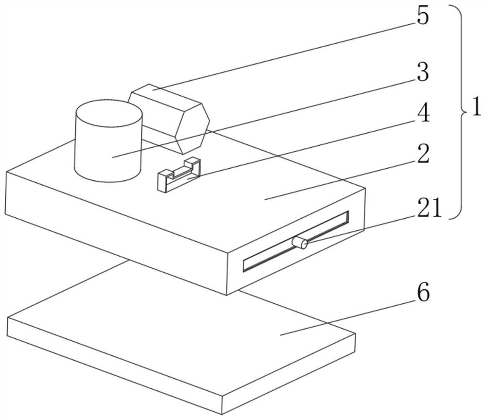
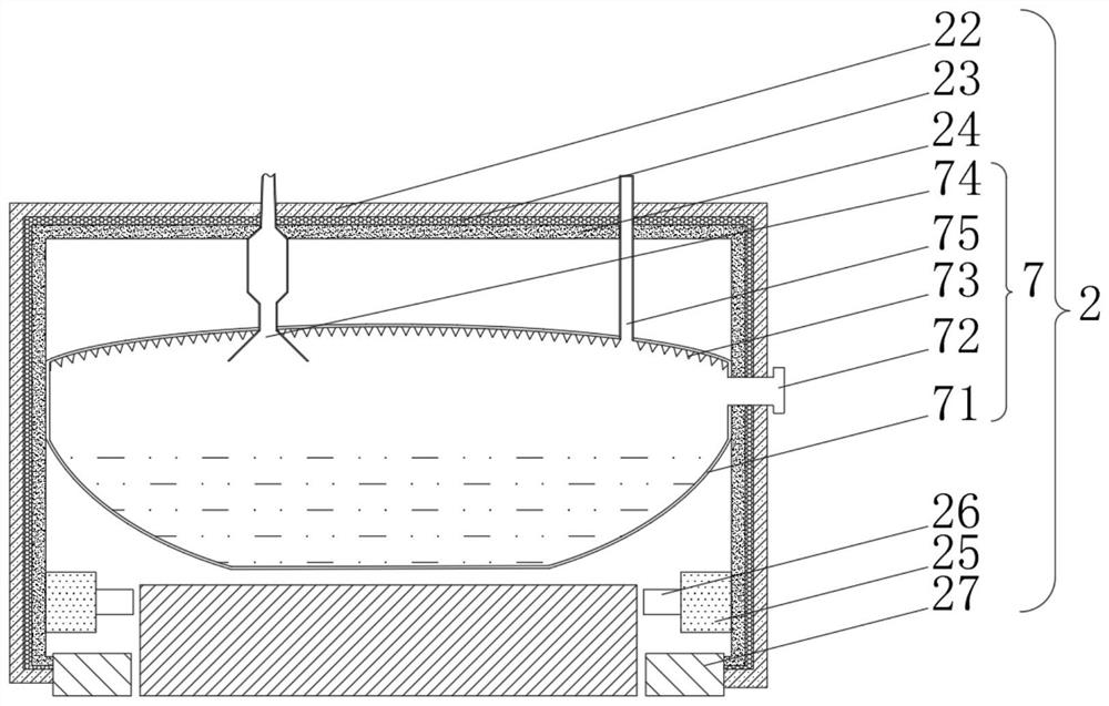
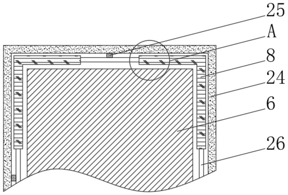
[0040] see Figure 1-3 The present invention provides a technical solution: a heat recovery device, including a heat recovery device body 1 composed of an incubator 2, a steam engine 3, a handle 4 and a generator 5, the bottom of the steam engine 3, the bottom of the handle 4 and the generator 5 The bottom is fixedly connected with the top of the incubator 2, the generator 5 is connected with the external storage battery, the steam engine 3 is connected with the generator 5, the right side of the incubator 2 is connected with a rotary switch 21, and the right side of the incubator 2 is provided with a The mold 6 is heated, and the incubator 2 includes an outer frame 22. The inner wall of the outer frame 22 is fixedly connected with an insulating cotton 23. The inner wall of the insulating cotton 23 is fixedly connected with a hydraulic shell 24. The inside of the hydraulic shell 24 is filled with insulating oil. The oil guide pipe 25 is connected inside, and the oil guide pipe...

Embodiment 2

[0046] see Figure 1-5 On the basis of the first embodiment, the present invention provides a technical solution: the clamping block 82 includes a clamping frame 821, the outside of the clamping frame 821 is slidably connected to the inside of the connecting frame 81, and the bottom of the clamping frame 821 is connected by a hard The mass block is fixedly connected with an elastic piece 822 , the bottom of the elastic piece 822 is fixedly connected with an extruding block 823 , and the bottom of the extruding block 823 is fixedly connected with a sliding plate 824 .

[0047] The buffer mechanism 9 is fixedly connected to the bottom of the sliding plate 824 , and the outer side of the sliding plate 824 is slidably connected to the inner wall of the clamping frame 821 .

[0048] When in use, the insulating oil inside the hydraulic casing 24 is squeezed by the piston, flows into the oil guide pipe 25, flows into the movable pipe 26, and flows into the inside of the connecting fr...

Embodiment 3

[0050] see Figure 1-7 , On the basis of Embodiment 1 and Embodiment 2, the present invention provides a technical solution: the buffer mechanism 9 includes an inner push block 91, the inside of the inner push block 91 is fixedly connected with a spring 92, and the bottom end of the spring 92 is fixedly connected with a The bottom of the outer pushing block 93 and the inner pushing block 91 are fixedly connected with an inner block 94 , and the top of the inner pushing block 94 is fixedly connected with the inside of the inner pushing block 91 .

[0051] The inside of the embedded block 94 is fixedly connected with a linkage frame 95, and the bottom of the linkage frame 95 is fixedly connected with an anti-collision block 96, and the top of the anti-collision block 96 is fixedly connected with an elastic ball 97, and the top of the elastic ball 97 is connected with the inner block 94. The top of the inner wall is fixedly connected, and the bottom of the outer pusher block 93 i...


PUM


Abstract

The invention discloses a heat recovery device, and relates to the technical field of waste heat treatment. The device comprises a heat recovery device body composed of a heat preservation box, a steam engine, a handle and a power generator, wherein the bottom of the steam engine, the bottom of the handle and the bottom of the power generator are all fixedly connected to the top of the heat preservation box, the power generator communicates with an external storage battery, the steam engine communicates with the power generator, and the right side of the heat preservation box is rotationally connected to a rotary switch. The heat recovery device solves the problems that in an existing factory such as a refrigerator factory, when an evaporator is produced, a vulcanization mold and a heating mold can be heated generally for 3-4 hours or even longer, in the electric heating process, only a heat preservation cover is used for covering the mold, the heating temperature is 300 DEG C to 400 DEG C, in the heating process, generated heat is directly dissipated into air, and after the mold is used, the mold is naturally cooled, a large amount of heat is dissipated into the air, and great heat waste is caused.

Description

technical field [0001] The invention relates to the technical field of waste heat treatment, in particular to a heat recovery device. Background technique [0002] Waste heat refers to the sensible heat and latent heat that have not been rationally utilized in the original design in the energy-consuming devices of public enterprises that have been put into operation; the generation of waste heat is mainly limited by production requirements and technical means; waste heat can be divided into high-temperature exhaust gas waste heat, cooling medium Waste heat, waste gas waste heat, high temperature products and slag waste heat, chemical reaction waste heat, waste gas waste heat and waste liquid waste heat, etc. According to the survey, the total waste heat resources of various industries account for about 17%-67% of the total gas fuel consumption, and the recyclable waste heat resources are about 60% of the total waste heat resources; in order to solve the current energy shorta...

Claims


Application Information

Patent Timeline
IPC IPC(8): F22B1/04F22B37/02B29C35/02
CPCF22B1/04F22B37/02B29C35/02B29C35/002Y02P70/10
Inventor 畅海峰
Owner 李燕秋
Learn More