Current measurement device and method, and manufacture method of current measurement device

The technology of a current measuring device and manufacturing method, which is applied in the field of electronic information, achieves the effect of broad application prospect and low cost

Inactive Publication Date: 2016-06-15
CHINA AGRI UNIV
7 Cites 2 Cited by

AI-Extracted Technical Summary

Problems solved by technology

[0004] Existing current clamp products that can measure current without power off are based on the pr...

Abstract

The present invention provides a current measurement device and method, and a manufacture method of a current measurement device. The device comprises: an elastic clamp, wherein the elastic clamp includes an elastic clamp body with a prefabricated circular binding clip and a clamp-type closed circular ring being inlaid on the circular binding clip of the elastic clamp body and being composed of a plurality of Hall elements; a signal processing additive circuit configured to obtain the Hall voltage of each Hall element when the elastic clamp is clamped the wires flowing through the current to be measured, obtain the current value to be measured based on the Ampere circuital theorem according to the Hall voltage of the Hall element and output the current to be measured to a display interface circuit; and the display interface circuit configured to obtain the current value to be measured outputted by the signal processing additive circuit and output the current value to be measured to the display device. The current measurement device is able to perform safe, simple, low-cost and efficient measurement of sorts of currents everywhere, and has wide application prospects.

Application Domain

Current/voltage measurement

Technology Topic

Measurement deviceInterface circuits +5

Image

  • Current measurement device and method, and manufacture method of current measurement device
  • Current measurement device and method, and manufacture method of current measurement device
  • Current measurement device and method, and manufacture method of current measurement device

Examples

  • Experimental program(1)

Example Embodiment

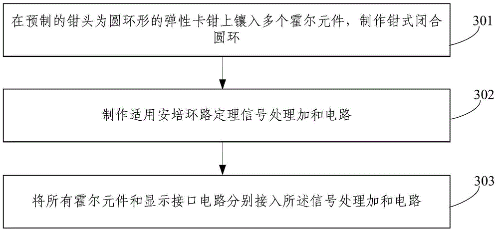
[0043] The specific embodiments of the present invention will be described in further detail below in conjunction with the drawings and embodiments. The following examples are used to illustrate the present invention, but not to limit the scope of the present invention.
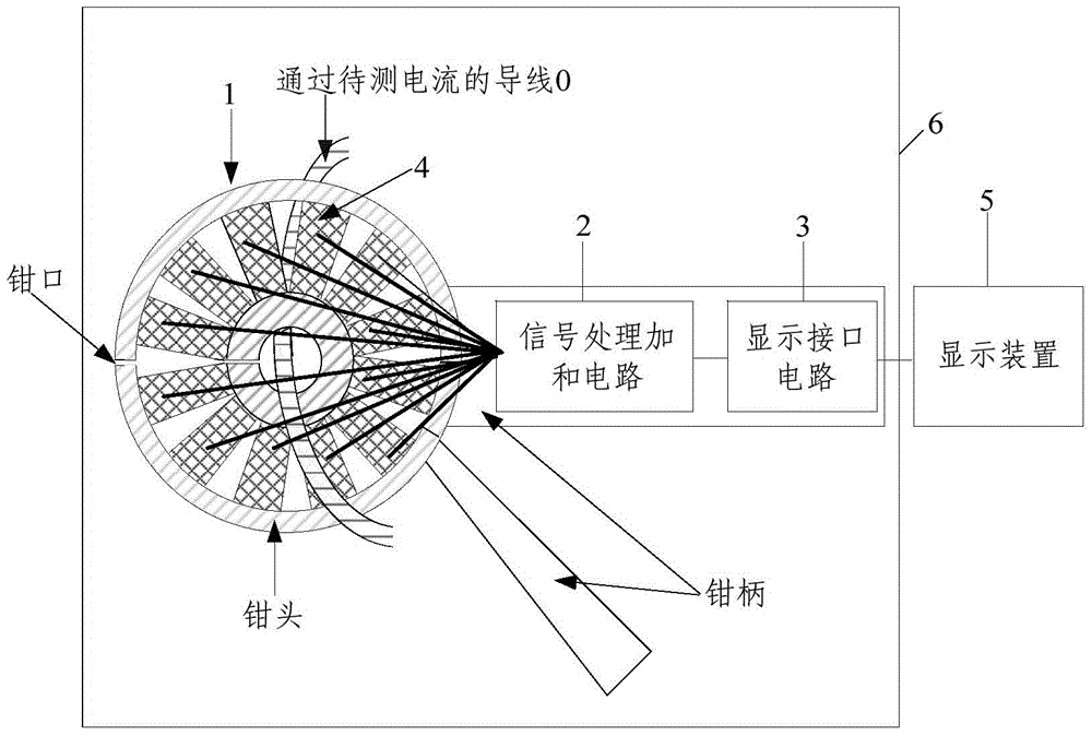
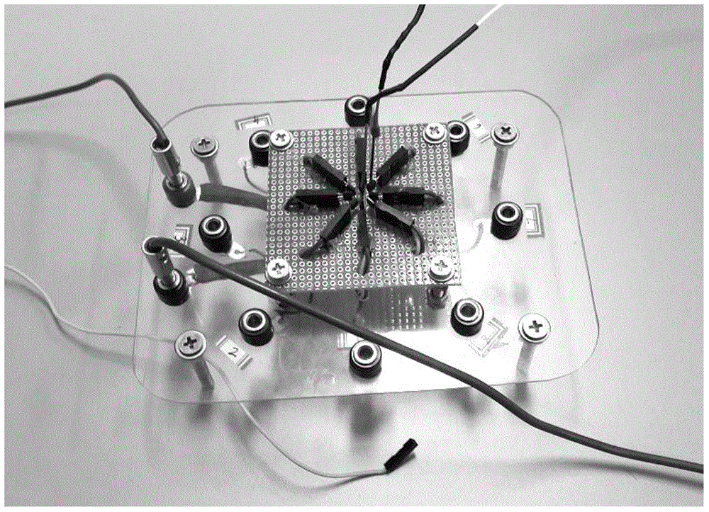
[0044] The value of the current I to be measured in the embodiment of the present invention is calculated according to the Ampere’s Loop Theorem. The Ampere’s Loop Theorem is specifically: the value of the integral of the magnetic induction B in space along any closed path (ie the circulating current value of B) is equal to The permeability μ multiplied by the algebraic sum of the currents enclosed by the closed path, namely If the current flow is in a right-handed spiral relationship with the integral loop, the current takes a positive value, otherwise it takes a negative value.
[0045] Because the integrated magnetoelectric sensor is getting smaller and smaller, so that people can measure the spatial distribution of the magnetic field more accurately. Experimental measurement.
[0046] The measuring principle of current according to the Ampere’s loop theorem in the embodiment of the present invention: adopt multiple (N) identical Hall sensor elements and arrange them into a circular closed loop with a radius of R; at this time, each Hall The component measured B is its tangential component B cut , Then each B Cut = kU (The output formula of the Hall element, k is the Hall sensitivity), dl=Rdθ, θ is each B cut The angle with dl; sum the product of the magnetic field measured by all Hall elements on the integration path
[0047] If there are N Hall elements, then According to the Ampere Loop Theorem: You can get
[0048] Therefore, by measuring the Hall voltage of each Hall element in real time, and adding the above formula, the current in the closed loop can be obtained.
[0049] figure 1 Is a schematic diagram of the structure of a current measuring device provided by an embodiment of the present invention, such as figure 1 As shown, the current measuring device 6 of this embodiment can be called a current clamp, and includes: an elastic clamp 1, a signal processing and summing circuit board 2 and a display interface circuit 3;
[0050] The elastic caliper 1 includes: a prefabricated caliper body with a circular ring shape and a pliers composed of a plurality of Hall elements 4 embedded on the circular ring pliers head of the elastic caliper body Closed ring
[0051] The signal processing and summing circuit 2 is used to obtain the Hall voltage of each Hall element 4 when the elastic clamp 1 clamps the wire 0 passing the current to be measured, and according to the Hall voltage of each Hall element 4 Obtain the current value to be measured based on the ampere loop theorem, and output the current value to be measured to the display interface circuit 3;
[0052] The display interface circuit 3 is used to obtain the current value to be measured output by the signal processing and summing circuit 2 and output the current value to be measured to the display device 5.
[0053] It should be noted that the display interface circuit 4 described in this embodiment is a common display interface circuit in the prior art.
[0054] In specific applications, the current measuring device of this embodiment may further include:
[0055] The display device 5 is used to obtain the current value to be measured output by the display interface circuit 3 and display the current value to be measured.
[0056] For example, the display device 5 may be a pointer display device or a digital liquid crystal display device.
[0057] In a specific application, the current I to be measured in this embodiment is:
[0058] I = R 2 π Nμ X i = 1 N k i U i ,
[0059] Wherein, R is the radius of the clamp-type closed ring, N is the number of the Hall element, μ is the magnetic permeability of the Hall element, k i Is the Hall sensitivity of each Hall element, μ, k i Is a constant, U i Is the Hall voltage of each Hall element, i=1, 2, ..., N, N is a positive integer greater than 1.
[0060] For example, the current measuring device 6 of this embodiment may include 8 Hall elements, such as figure 2 As shown, figure 2 Shows a physical diagram of a current measurement device with 8 Hall elements provided by an embodiment of the present invention. In order to verify that the current measurement device 6 based on the ampere loop theorem in the present invention is feasible, you can use figure 2 The current measuring device of this embodiment including 8 Hall elements is shown to measure the energized current (amperes) of the center wire. The experimental data is shown in Table 1.
[0061] Table 1
[0062]
[0063] Using the measured data, according to the formula in the principle The calculated current value is 0.96A, which is not much different from the actual current 1A. The effective feasibility of the current measuring device described in the embodiment of the present invention is confirmed. The reason for this error is that there is a large gap between the eight Hall elements arranged, which makes the loop measurement of the magnetic field not accurate enough. If the present invention is implemented The current measuring device described in the example is made seamless, which will greatly reduce the error and improve the measurement accuracy.
[0064] The current measuring device 6 of this embodiment, according to the ampere loop theorem, can measure current by measuring the magnetic field of a closed loop. We can connect many Hall elements 4 tightly together to form a symmetrical closed ring. Make this ring on the head of the clamp. When measuring, you only need to press the handle of the clamp and let the current clamp clamp a certain current-carrying wire to measure the current in it; especially for DC current, you can Real-time display of its current value; for current changes (such as lightning, and various waveform currents, etc.), real-time data acquisition and recording can be performed, and its effective value can be displayed in real time.
[0065] The current measuring device of this embodiment can reduce the danger caused by the measurement method of connecting the ammeter (especially in the case of strong current, such as lightning surge current monitoring), and avoid the measurement of connecting the ammeter after the circuit is broken. The method is troublesome, does not need to suspend the work of the equipment, greatly improves the measurement efficiency, and is simple and easy to implement, low in cost, and has a very broad application prospect.
[0066] image 3 Shows that provided by an embodiment of the present invention figure 1 The flow chart of the manufacturing method of the current measuring device shown, such as image 3 As shown, the manufacturing method of the current measuring device of this embodiment is as follows.
[0067] 301. A plurality of Hall elements are inserted into the elastic caliper body with the prefabricated pliers head in a circular ring shape to make a pliers-type closed ring.
[0068] 302. Make a signal processing and summing circuit applicable to the Ampere Loop Theorem.
[0069] 303. Connect all Hall elements and display interface circuits to the signal processing and summing circuit respectively.
[0070] It should be noted that the display interface circuit described in this embodiment is a common display interface circuit in the prior art.
[0071] It should be noted that after step 303, the circuit parameters should be adjusted so that the signal processing and summing circuit outputs the current value to be measured through the display interface circuit.
[0072] In specific applications, the method described in this embodiment, after step 303, may also include Figure 4 Step 304 shown:
[0073] 304. Connect the display interface circuit with a display device.
[0074] For example, the display device may be:
[0075] Pointer type display device or digital liquid crystal display device.
[0076] In a specific application, the value of the current I to be measured in this embodiment is:
[0077] I = R 2 π Nμ X i = 1 N k i U i ,
[0078] Wherein, R is the radius of the clamp-type closed ring, N is the number of the Hall element, μ is the magnetic permeability of the Hall element, k i Is the Hall sensitivity of each Hall element, μ, k i Is a constant, U i Is the Hall voltage of each Hall element, i=1, 2, ..., N, N is a positive integer greater than 1.
[0079] The manufacturing method of the current measuring device of this embodiment is used to manufacture figure 1 The current measuring device shown can be safe, simple, low-cost, high-efficiency and real-time measurement of various currents everywhere, and its application prospects are broad.
[0080] Figure 5 Use provided for an embodiment of the present invention figure 1 The flow diagram of the current measuring method of the current measuring device shown, such as Figure 5 As shown, the current measurement method of this embodiment is as follows.
[0081] 501. Obtain the Hall voltage of each Hall element when the elastic clamp inserted into the plurality of Hall elements clamps the wire passing the current to be measured.
[0082] 502. Calculate the current value to be measured based on the Ampere Loop Theorem according to the Hall voltage of each Hall element, so that the current value to be measured passing through the display interface circuit is displayed on the display device.
[0083] Wherein, the plurality of Hall elements form a clamp-type closed ring after being inserted into the circular clamp head of the elastic clamp body.
[0084] In a specific application, the value of the current I to be measured in this embodiment is:
[0085] I = R 2 π Nμ X i = 1 N k i U i ,
[0086] Wherein, R is the radius of the clamp-type closed ring, N is the number of the Hall element, μ is the magnetic permeability of the Hall element, k i Is the Hall sensitivity of each Hall element, μ, k i Is a constant, U i Is the Hall voltage of each Hall element, i=1, 2, ..., N, N is a positive integer greater than 1.
[0087] The current measurement method of this embodiment uses figure 1 The current measuring device described in the illustrated device embodiment can measure various currents everywhere in a safe, simple, low-cost, high-efficiency and real-time manner, and its application prospects are broad.
[0088] Finally, it should be noted that the above embodiments are only used to illustrate the technical solutions of the present invention, but not to limit them; although the present invention has been described in detail with reference to the foregoing embodiments, those of ordinary skill in the art should understand: It is still possible to modify the technical solutions described in the foregoing embodiments, or equivalently replace some or all of the technical features; these modifications or replacements do not cause the essence of the corresponding technical solutions to deviate from the scope of protection of the claims of the present invention .

PUM

no PUM

Description & Claims & Application Information

We can also present the details of the Description, Claims and Application information to help users get a comprehensive understanding of the technical details of the patent, such as background art, summary of invention, brief description of drawings, description of embodiments, and other original content. On the other hand, users can also determine the specific scope of protection of the technology through the list of claims; as well as understand the changes in the life cycle of the technology with the presentation of the patent timeline. Login to view more.

Similar technology patents

Apparatus and method for low-density cellular wood plastic composites

InactiveUS20050067729A1less-expensivelow cost
Owner:STRANDEX CORP

Haptic trackball device

InactiveUS7710399B2simple actuatorlow cost
Owner:IMMERSION CORPORATION

Steering Arrangement for a Trailer

InactiveUS20110018231A1low cost
Owner:ZF FRIEDRICHSHAFEN AG

Classification and recommendation of technical efficacy words

  • Broad application prospects
  • low cost

Large unsaturated seepage physical simulator for soil in aerated zone

InactiveCN102636630AImprove hands-on abilityBroad application prospects
Owner:CHINA UNIV OF GEOSCIENCES (WUHAN)

System and method for transmitting wireless digital service signals via power transmission lines

ActiveUS7929940B1reduce bandwidth requirementlow cost
Owner:NEXTEL COMMUNICATIONS

System and method for determination of position

InactiveUS20090149202A1low costreduce requirement
Owner:STEELE CHRISTIAN

Adaptive antenna optimization network

InactiveUS6961368B2low costminimal space
Owner:ERICSSON INC

Antenna device and method for attaching the same

ActiveUS20150138022A1low costimproved strength characteristic
Owner:NEC CORP
Why Eureka
Try Eureka