
Fault monitoring system for power transmission line

A transmission line and fault monitoring technology, applied in the direction of fault location, fault detection according to conductor type, etc., can solve the problems affecting the stable operation of the line and the heavy workload of line inspection, so as to reduce the labor intensity of line inspection, improve work efficiency and save money. The effect of human and material resources

Inactive Publication Date: 2016-06-15
ZHANGQIU POWER SUPPLY CO OF STATE GRID SHANDONG ELECTRIC POWER CO
View PDF6 Cites 11 Cited by
  • Summary
  • Abstract
  • Description
  • Claims
  • Application Information

AI Technical Summary

Problems solved by technology

Although the traditional fault indicator can indicate the fault current flowing through the line through the optical plate, it still needs to inspect the line to find the fault section, and the workload of the line inspection is still very large, which affects the stable operation of the line

Method used


Image

  • Fault monitoring system for power transmission line
  • Fault monitoring system for power transmission line
  • Fault monitoring system for power transmission line

Examples


Embodiment Construction

[0031] In order to make the purpose, features and advantages of the present invention more obvious and understandable, the technical solutions protected by the present invention will be clearly and completely described below using specific embodiments and accompanying drawings. Obviously, the implementation described below Examples are only some embodiments of the present invention, but not all embodiments. Based on the embodiments in this patent, all other embodiments obtained by persons of ordinary skill in the art without creative efforts fall within the protection scope of this patent.

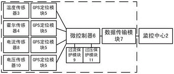
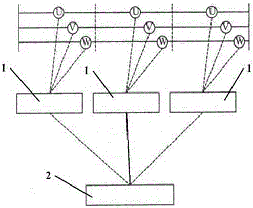
[0032] This embodiment provides a transmission line fault monitoring system, such as figure 1 , figure 2 , image 3 As shown, as shown, including: a transmission line signal acquisition device 1 and a monitoring center 2;

[0033] The transmission line signal acquisition device 1 includes: a temperature sensor 3, a Hall sensor 4, a fault indicator light, a microcontroller 6, a GPS posi...


PUM


Abstract

Disclosed in the invention is a fault monitoring system for a power transmission line. The fault monitoring system comprises a transmission line signal collecting device and a monitoring center. The transmission line signal collecting device consists of a temperature sensor, a hall sensor, a fault indicator light, a microcontroller, a GPS positioning module, and a data transmission module; the microcontroller receives fault signals sent by the temperature sensor and the hall sensor; a line fault position is obtained by the GPS positioning module; and the data transmission module sends the fault signals and the line fault position to the monitoring center. After a fault occurs within a few minutes, a fault position can be provided and then the fault point information is sent to the monitoring center, so that the maintenance staff can go to the field rapidly and thus a potential failure can be eliminated. Therefore, reliable and effective data can be provided for the operation staff and the maintenance staff to carry out operation and maintenance, fault analyses, and line repairing, thereby substantially improving the operation reliability of the power transmission line.

Description

technical field [0001] The invention relates to the field of power transmission lines, in particular to a power transmission line fault monitoring system. Background technique [0002] In recent years, with the rapid development of economy, the power industry is facing more and more pressure. The continuous increase of power supply load requires more reliability of power supply. However, in the power transmission operation system, there are many branches of the line, the operation mode is complicated, the distance of the overhead transmission line is long, the distribution is wide, the terrain is complex, and the line inspection is difficult. Phase-to-phase short-circuits or single-phase ground faults often occur in transmission lines under harsh weather and environmental conditions, and the instantaneous faults exceed 80%. The local insulation damage caused by such faults generally has no obvious traces, which brings great difficulties to the search. [0003] How to quick...

Claims


Application Information

Patent Timeline
Patent Type & Authority Applications(China)
IPC IPC(8): G01R31/08
CPCG01R31/085
Inventor 仇法永隗永马军赵天珍王刚韩波卢春艳胡海舰王兰国
Owner ZHANGQIU POWER SUPPLY CO OF STATE GRID SHANDONG ELECTRIC POWER CO
Learn More