
Relay fault detection circuit and detection method thereof

A relay fault detection circuit technology, applied in the direction of circuit breaker testing, etc., can solve the problems of time and cost increase, false alarm, danger, etc., and achieve the effect of reducing requirements

Inactive Publication Date: 2016-06-15
HELLA SHANGHAI ELECTRONICS
View PDF5 Cites 26 Cited by
  • Summary
  • Abstract
  • Description
  • Claims
  • Application Information

AI Technical Summary

Problems solved by technology

[0006] 1) False alarm problem, maybe the network failure is not caused by the relay itself, it may be caused by the coupling failure of other components;
[0007] 2) Safety issues. In the process of fault detection, the system cannot be considered to be in a safe state, but in order to detect the state of the relay, it is necessary to power on the high-voltage network, so this state may bring the danger of high-voltage leakage;
Both time and expense costs will be greatly increased, and this method has a certain degree of blindness

Method used


Image

  • Relay fault detection circuit and detection method thereof
  • Relay fault detection circuit and detection method thereof
  • Relay fault detection circuit and detection method thereof

Examples


Embodiment Construction

[0029] The advantages of the present invention will be further elaborated below in conjunction with the accompanying drawings and specific embodiments.

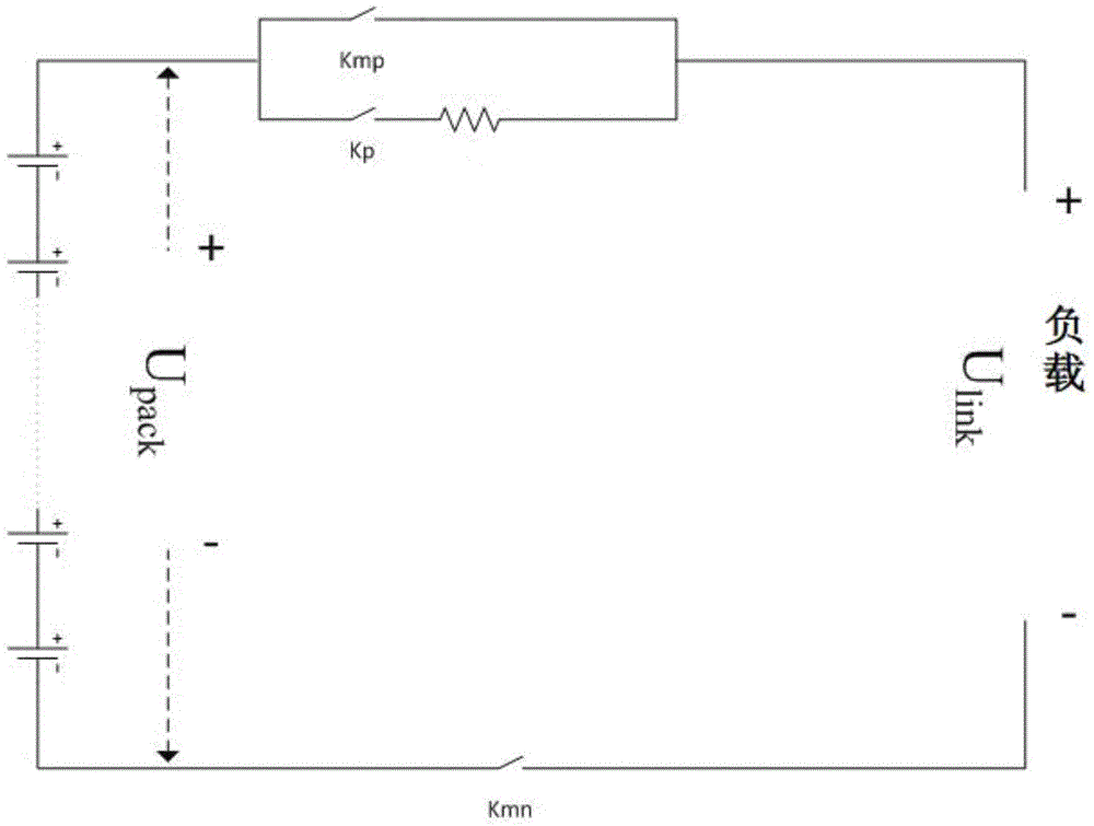
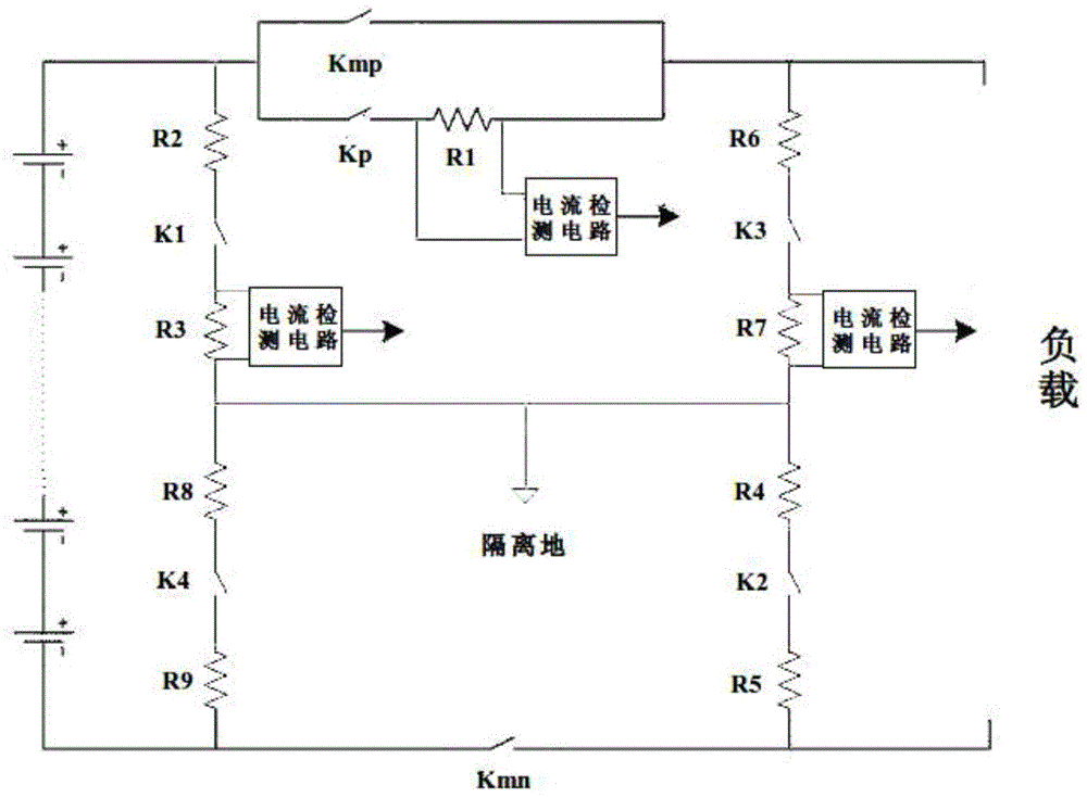
[0030] refer to figure 2 , is a schematic circuit diagram of the relay fault detection circuit in the present invention. The relay fault detection circuit includes a power supply that provides electric energy, loads connected to both ends of the power supply, and the main positive relay Kmp and main negative relay Kmn that control the power supply of the engine in the DC high-voltage or low-voltage electrical network, and are used to suppress the inrush protection control device. Precharge relay Kp. The main positive relay Kmp and the pre-charging relay Kp are connected in series between the power supply and the load, and the main negative relay Kmn is connected in series between the power supply and the load. In order to detect the fault of the relay, the circuit also includes a sampling circuit module, which detects the ...


PUM


Abstract

The present invention provides a relay fault detection circuit and a detection method thereof. The circuit comprises a power supply, a load, a master positive relay Kmp, a pre-charge relay Kp, a master negative relay Kmn and a sampling circuit module; the sampling circuit module includes a first sampling loop, a second sampling loop and a second sampling circuit which is connected in series with the pre-charge relay Kp; one end of the first sampling loop is connected between the power supply and the master positive relay Kmp, and the other end of the first sampling loop is connected between the load and the master negative relay Kmn; and one end of the second sampling loop is connected between the load and the master positive relay Kmp, the other end of the second sampling loop is connected between the power supply and the master negative relay Kmn, and the first sampling loop and the second sampling loop are respectively conducted to detect sampling resistance R1 and the voltages of the first sampling loop and the second sampling loop so as to determine whether the master positive relay Kmp, the pre-charge relay Kp and the master negative relay Kmn are adhered or jammed or not.

Description

technical field [0001] The invention relates to the field of automotive electronic control, in particular to a relay fault detection circuit and a detection method thereof. Background technique [0002] With the rapid development of new energy vehicles such as electric vehicles (hybrid vehicles), the safety requirements of the DC drive part are becoming more and more stringent, and the fault diagnosis and detection of the high-voltage relay of the DC power control unit are becoming more and more important. [0003] However, the traditional relay detection has its great limitations. Traditional relay detection is mainly divided into two categories: one is to judge by the state of the relay itself, the pull-in / release voltage or contact pressure; the other is to judge the state of the relay group by detecting the output voltage of the entire system network , that is, to detect whether Upack is equal to Ulink, the system network schematic diagram is as follows figure 1 shown....

Claims


Application Information

Patent Timeline
IPC IPC(8): G01R31/327
Inventor 杨新哲赵雪连
Owner HELLA SHANGHAI ELECTRONICS
Features
  • Generate Ideas
  • Intellectual Property
  • Life Sciences
  • Materials
  • Tech Scout
  • Unparalleled Data Quality
  • Higher Quality Content
  • 60% Fewer Hallucinations
Learn More