Environment monitoring system capable of achieving continuous working

An environmental monitoring and system connection technology, applied in photovoltaic power generation, electrical components, electro-solid devices, etc., can solve the problems of inefficient use of outdoor solar energy resources, lack of solar cell modules, etc., to improve capacity, improve collection efficiency, The effect of increasing the contact area

Inactive Publication Date: 2016-06-15
吴桂广
View PDF4 Cites 0 Cited by
  • Summary
  • Abstract
  • Description
  • Claims
  • Application Information

AI Technical Summary

Problems solved by technology

[0003] Under normal circumstances, the working place of the environmental monitoring system is an outdoor area. However, the existing environmental monitoring systems generally do not have solar cell modules and cannot efficiently utilize outdoor solar energy resources.

Method used


Image

  • Environment monitoring system capable of achieving continuous working

Examples


Embodiment 1

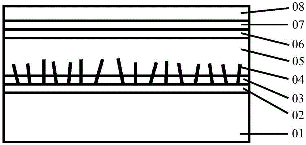
[0034] Such as figure 1 As shown, an environment monitoring system capable of continuous operation provided by an embodiment of the present invention is characterized in that a polymer solar cell is installed on the outer surface of the environment monitoring system, and the ITO glass side of the polymer solar cell Installed toward the outside, the polymer solar cell is connected to the environmental monitoring system through wires; the polymer solar cell is a sandwich structure consisting of an anode electrode, an organic active layer, and a cathode electrode; the anode electrode is ITO from outside to inside. Glass (01), WO X Film (02), WO X Nanowire film (04), PEDOT:PSS buffer layer (03), wherein, WO X Nanowire films (04) grown on WO X On the film (02), a PEDOT:PSS buffer layer (03) is filled between the nanowire structures, and the length of the nanowire is greater than the thickness of the PEDOT:PSS buffer layer (03); the organic active layer (05) is located between th...

Embodiment 2

[0049] An environmental monitoring system capable of continuous operation provided by an embodiment of the present invention is characterized in that a polymer solar cell is installed on the outer surface of the environmental monitoring system, and the ITO glass side of the polymer solar cell is installed facing the outside , the polymer solar cell is connected to the environmental monitoring system through wires; the polymer solar cell is a sandwich structure consisting of an anode electrode, an organic active layer, and a cathode electrode; the anode electrode is made of ITO glass (01 ), WO X Film (02), WO X Nanowire film (04), PEDOT:PSS buffer layer (03), wherein, WO X Nanowire films (04) grown on WO X On the film (02), a PEDOT:PSS buffer layer (03) is filled between the nanowire structures, and the length of the nanowire is greater than the thickness of the PEDOT:PSS buffer layer (03); the organic active layer (05) is located between the anode electrode and Between the ...

Embodiment 3

[0064] An environmental monitoring system capable of continuous operation, characterized in that, a polymer solar cell is installed on the outer surface of the environmental monitoring system, the ITO glass side of the polymer solar cell is installed facing the outside, and the polymer solar cell is installed through a wire It is connected with the environmental monitoring system; the polymer solar cell is a sandwich structure consisting of an anode electrode, an organic active layer and a cathode electrode; the anode electrode is ITO glass (01), WO X Film (02), WO X Nanowire film (04), PEDOT:PSS buffer layer (03), wherein, WO X Nanowire films (04) grown on WO X On the film (02), a PEDOT:PSS buffer layer (03) is filled between the nanowire structures, and the length of the nanowire is greater than the thickness of the PEDOT:PSS buffer layer (03); the organic active layer (05) is located between the anode electrode and Between the cathode electrodes, the thickness of the orga...


PUM


Abstract

The invention discloses an environment monitoring system capable of achieving continuous working. A polymer solar cell is arranged on the outer surface of the environment monitoring system, and is in a sandwich structure; the polymer solar cell comprises an anode electrode, an organic active layer and a cathode electrode; the anode electrode is sequentially provided with ITO glass, a WOX film, a WOX nanowire film and a PEDOT:PSS buffer layer from the outside to the inside; the organic active layer is located between the anode electrode and the cathode electrode; and the cathode electrode is sequentially provided with a Ti sheet, an Al film and a TiO<2> film from the outside to the inside. The polymer solar cell can provide a power support for the environment monitoring system, so that the continuous working target is achieved; and the environment monitoring system is high in the energy conversion efficiency, good in the stability, and relatively long in cycle working time and lifetime.

Description

technical field [0001] The invention relates to the monitoring field, in particular to an environment monitoring system capable of realizing continuous work. Background technique [0002] The environmental monitoring system includes a data acquisition part, a signal processing part, a monitoring part, etc. It is a monitoring of environmental parameters in a certain area, including continuous observation of conventional meteorological elements (wind direction, wind speed, humidity, etc.). [0003] Generally, the working place of the environmental monitoring system is an outdoor area. However, the existing environmental monitoring systems generally do not have solar cell modules, and cannot efficiently utilize outdoor solar energy resources. Contents of the invention [0004] The purpose of the present invention is to avoid the disadvantages of the prior art and provide an environment monitoring system that can realize continuous work. [0005] The object of the present inv...

Claims


Application Information

Patent Timeline
Patent Type & Authority Applications(China)
IPC IPC(8): H01L51/44H01L51/48
CPCH10K30/81H10K30/00H10K30/82Y02E10/549
Inventor 吴桂广
Owner 吴桂广
Why Eureka
Try Eureka