
Radial supporting and axial pre-tightening structure for dynamic balance measurement of motor rotor provided with bearing

A rotor dynamic balance and radial support technology, which is applied in the direction of electric components, manufacturing motor generators, centering/balancing rotors, etc., can solve the problem that the unilateral preload cannot be transmitted, the processing technology requirements are very high, and the unilateral thrust pin Problems such as suspension, to achieve the effect of reducing processing technology requirements, improving consistency and stability, and reducing beating

Active Publication Date: 2016-06-15
杭州集智机电股份有限公司
View PDF7 Cites 16 Cited by
  • Summary
  • Abstract
  • Description
  • Claims
  • Application Information

AI Technical Summary

Problems solved by technology

However, this structure has great disadvantages. First, the structure has high requirements on its own processing technology. When the cylinder is pressed, the two thrust pins must be supported on the end face of the bearing outer ring at the same time. Once there is a processing deviation or assembly deviation, It is easy to make the thrust pin on one side hang in the air, so that the preload force on one side cannot be transmitted, the force on both sides of the bearing is too different, and the measurement data is unreliable

Method used


Image

  • Radial supporting and axial pre-tightening structure for dynamic balance measurement of motor rotor provided with bearing
  • Radial supporting and axial pre-tightening structure for dynamic balance measurement of motor rotor provided with bearing
  • Radial supporting and axial pre-tightening structure for dynamic balance measurement of motor rotor provided with bearing

Examples


Embodiment Construction

[0027] The present invention will be further described in conjunction with the accompanying drawings and embodiments.

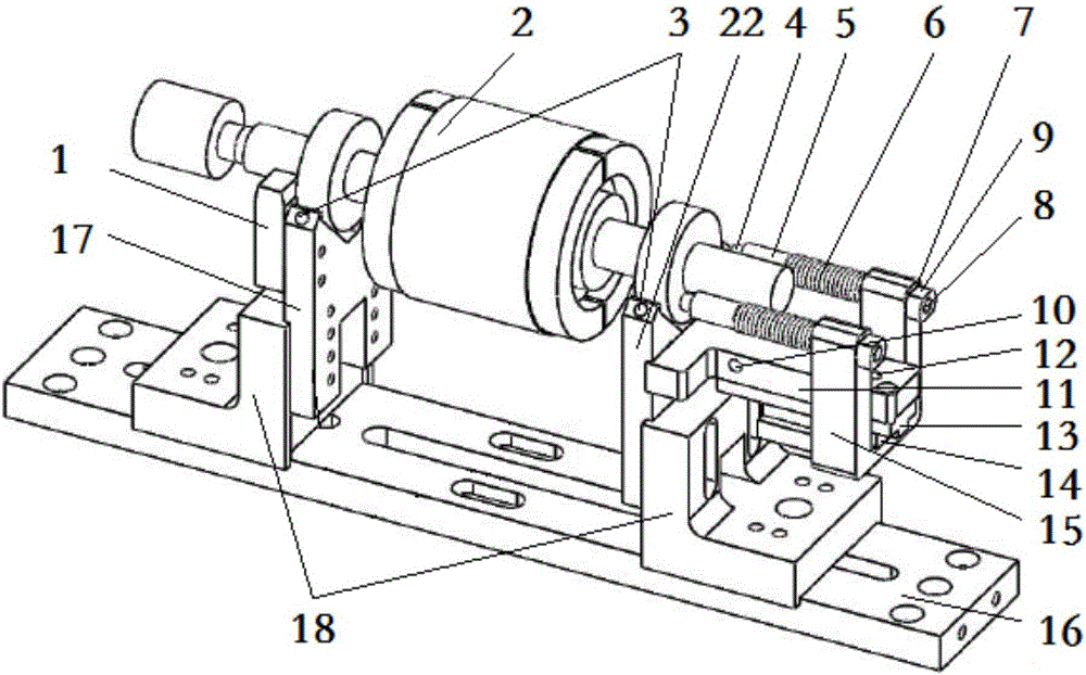
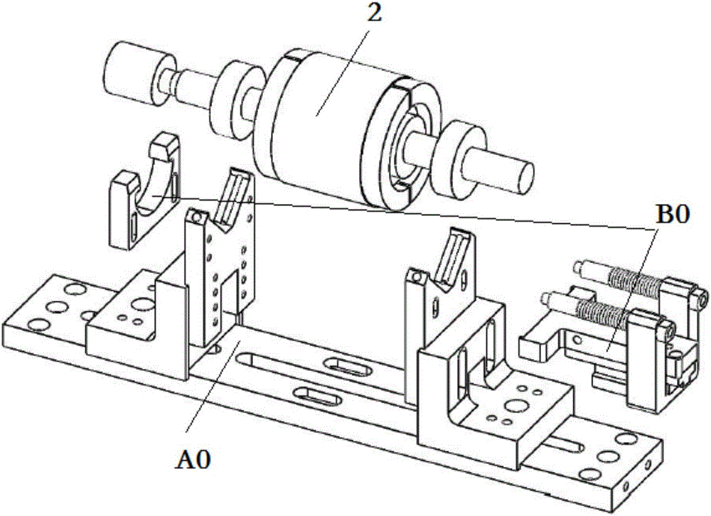
[0028] Such as figure 2 As shown, the present invention includes a rotor bearing radial support structure A0 and a rotor bearing axial preload structure B0, the motor rotor 2 is supported and installed on the rotor bearing radial support structure A0 for radial support, and is mounted on the rotor bearing radial The rotor bearing axial preloading structure B0 on ​​the supporting structure A0 performs axial preloading.

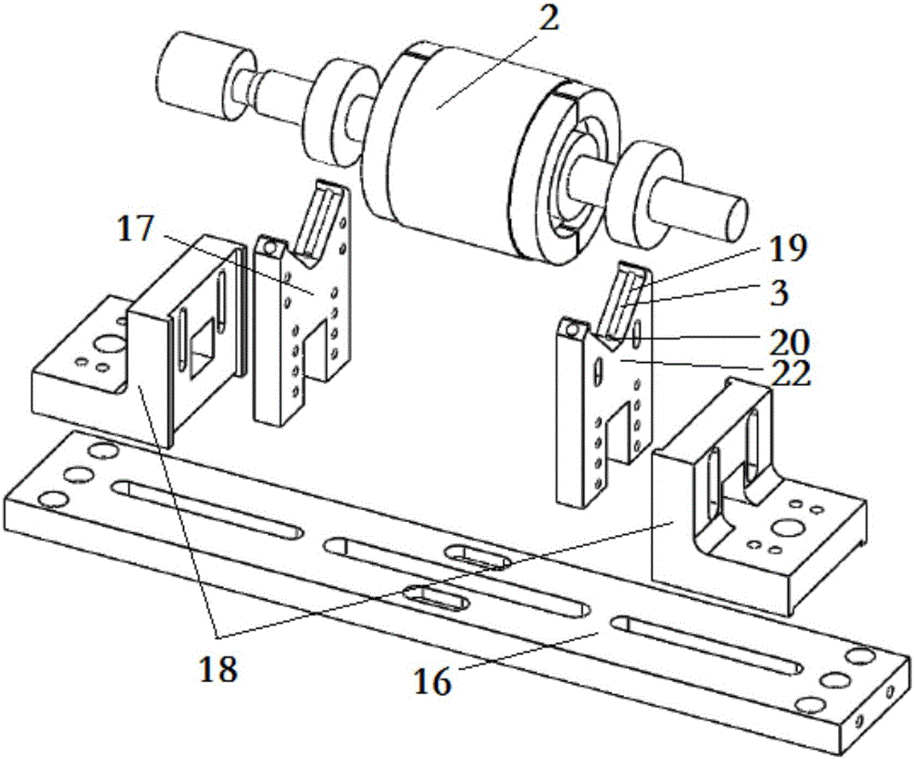
[0029] Such as figure 1 with image 3 As shown, the rotor bearing radial support structure A0 includes a tungsten steel rod 3, a radial support frame 17 on the blocking shaft side, a radial support frame 22 on the top shaft side, a radial support frame base 18 and a floating platform bottom plate 16, two radial The supporting frame base 18 is installed on both sides of the floating platform bottom plate 16 respectively, according to the di...


PUM


Abstract

The invention discloses a radial supporting and axial pre-tightening structure for dynamic balance measurement of a motor rotor provided with a bearing. The motor rotor is mounted on a rotor bearing radial support structure in a supported manner for radial support, a rotor bearing axial pre-tightening structure mounted on the rotor bearing radial support structure is used for axial pre-tightening, the rotor bearing radial support structure makes point contact with a cylindrical surface in the outer ring of the motor rotor bearing via tungsten steel bars in bar-shaped grooves of radial support frames at two sides, the rotor bearing axial pre-tightening structure comprises a baffle plate mounted at the outer side surfaces of the radial support frame at the bearing limiting side and an axial pre-tightening assembly mounted at the radial support frame at the bearing abutting side, the baffle plate limits the bearing at one end of the motor rotor in the axial direction, and the axial pre-tightening assembly pre-tightens the bearing at the other end of the motor rotor in the axial direction. The radial supporting and axial pre-tightening structure improves the consistency and stability of the pre-tightening state during dynamic balance measurement of the motor rotor provided with the bearing, the fluctuation degree of dynamic balance measurement of the motor rotor is reduced, and the repeatability and reproducibility of measurement are improved.

Description

technical field [0001] The invention relates to a radial support and axial pretightening structure, in particular to a radial support and axial pretightening structure for the dynamic balance measurement of a motor rotor with installed bearings. Preload. Background technique [0002] The motor is an important production and daily necessities, and the rotor is an important working part of the motor. In the production process of the rotor, due to reasons such as unreasonable design, uneven material, and processing and assembly errors, there is inevitably an initial imbalance. The rotor with excessive unbalance will generate vibration and noise during the operation of the motor, which will degrade the performance of the motor in light cases, and cause damage and accidents in severe cases. Therefore, the rotor must be dynamically balanced to maintain the unbalanced amount at within the qualified range. [0003] Rotor dynamic balance correction equipment can be divided into tw...

Claims


Application Information

Patent Timeline
IPC IPC(8): H02K15/16
CPCH02K15/165
Inventor 赵良梁张加庆沈俊杰李宝娟陆兴
Owner 杭州集智机电股份有限公司
Learn More