Alternating current brushless double-fed motor and design method for tooth harmonic coil-wound rotor distributed winding therefor

A technology of a doubly-fed machine and a design method, which is applied to the shape/style/structure of winding conductors, electric components, asynchronous induction motors, etc., can solve the problems of unequal number of coil turns, complex structure, irregular overlapping of ends, etc. Achieve the effects of low harmonic content, high conductor utilization, and neat structure and shape

Inactive Publication Date: 2016-06-15
HUAZHONG UNIV OF SCI & TECH +1
View PDF5 Cites 8 Cited by
  • Summary
  • Abstract
  • Description
  • Claims
  • Application Information

AI Technical Summary

Problems solved by technology

[0005] Aiming at technical defects, the purpose of the present invention is to provide a design method of AC brushless doubly-fed motor and its wound rotor winding, aiming at solv

Method used


Image

  • Alternating current brushless double-fed motor and design method for tooth harmonic coil-wound rotor distributed winding therefor
  • Alternating current brushless double-fed motor and design method for tooth harmonic coil-wound rotor distributed winding therefor
  • Alternating current brushless double-fed motor and design method for tooth harmonic coil-wound rotor distributed winding therefor

Examples


example 1

[0066] Example 1 design p 1 = 1 and p 2 = 3 tooth harmonic wound rotor winding scheme

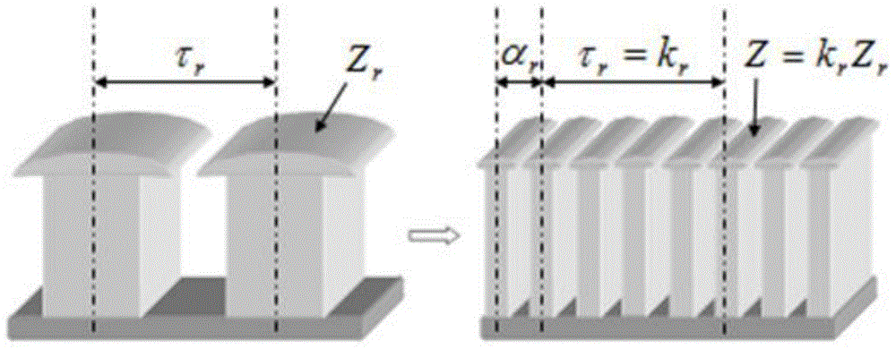
[0067] here p r =p 1 +p 2 = 4, take k r =τ r =20, then Z=k r Z r =80, assuming n r = 11 and y r =16r , at this time The results of harmonic analysis of winding magnetomotive force are shown in Table 2. As can be seen from Table 2, p 1 = 1 The winding coefficient is 0.5698, p 2 =3 The winding factor is 0.7080.

[0068] table 280 slot p 1 / p 2 = 1 / 3 distributed tooth harmonic winding magnetomotive force harmonic analysis

[0069]

[0070]

[0071] because y r =16r , so the concentric winding method can be used, and the pitch of each large and small coil of each phase winding is according to the formula y=y r +n r -(2n-1) calculation, n=1 corresponds to the coil with the largest pitch y=26, n=n r Corresponding to the coil with the minimum pitch y=6, the specific coil expansion layout is as follows Figure 4 shown. from Figure 4 It can be seen that the adjacent ph...

example 2

[0072] Example 2 design p 1 = 2 and p 2 = 4 tooth harmonic wound rotor winding scheme

[0073] here p r =p 1 +p 2 = m r = 6, take k r =14, then Z=k r Z r =84, in order to make the harmonic content in the rotor magnetomotive force small and have a high conductor utilization rate, the scheme of combining two sets of windings in series is adopted. One set of windings takes n r =8 and y r =12, another set of windings takes n r = 5 and y r =9, then The results of harmonic analysis of winding magnetomotive force are shown in Table 3. As can be seen from Table 3, p 1 = 2 The winding coefficient is 0.6878, p 2 =4 The winding coefficient is 0.8106, while the relative amplitude of the main high-order tooth harmonics is <4%.

[0074] Table 384 slot p 1 / p 2 = 2 / 4 distributed tooth harmonic winding magnetomotive force harmonic analysis

[0075]

[0076]

[0077] The winding coil still adopts the concentric winding method, according to the calculation formula y=y ...


PUM


Abstract

The invention discloses an alternating current brushless double-fed motor and a design method for a tooth harmonic coil-wound rotor distributed winding therefor. The design method comprises the steps that the number Zr of rotor toothed slots and the phase number mr are preliminarily determined according to stator winding pole pair numbers p1 and p2, wherein Zr is equal to mr at the current moment; each tooth is corresponding to a concentrated coil, so that a tooth harmonic concentrated type winding is obtained; then the number of rotor slots is increased, a coefficient kr is chosen to enable a new number of rotor slots Z to be equal to krZr, wherein the polar distance at the current moment tau r is equal to kr; on the basis, one concentrated coil in each phase is split into nr coils with the equipment pitch of yr, wherein nr is less than or equal to kr, and yr is less than tau r; the nr coils are distributed in the rotor slots in sequence at interval of alpha r slot pitch angle; then the kr, nr and yr are adjusted to enable the winding coefficient of the pole pair numbers p1 and p2 to be as high as possible, and the harmonic content is low; and finally, the winding coils in each phase are wound by adopting a multi-plane concentric type winding method to obtain coils with different pitches and different sizes and with overlaid central lines, and then the obtained coils are put in the rotor slots, connected in series and then linked in a short-circuited manner to obtain the distributed tooth harmonic rotor winding. The distributed tooth harmonic rotor winding has the characteristics of low harmonic content, high conductor utilization ratio and tidy winding end part arrangement.

Description

technical field [0001] The invention belongs to the technical field of AC brushless doubly-fed motors, and more particularly relates to a design method of AC brushless doubly-fed motors and wound rotor windings thereof. Background technique [0002] The brushless doubly-fed motor is powered by grid power and variable frequency power supply separately. It has the characteristics of reliable operation, requires a small capacity of variable frequency power supply, and can adopt different voltage levels. , used for wind power or hydraulic variable speed constant frequency power generation, etc. [0003] The key to the good performance of brushless doubly-fed motors lies in the rotor; in terms of working principle, the rotor types can be divided into reactive and inductive, and there are mainly two specific rotor structures studied in recent years, one is reactive The reluctance rotor, the rotor core is made into a structure similar to salient poles, without any conductors on it...

Claims


Application Information

Patent Timeline
IPC IPC(8): H02K17/12H02K3/28H02K15/095
CPCH02K3/28H02K15/095H02K17/12H02K2213/03
Inventor 王雪帆金维宇熊飞
Owner HUAZHONG UNIV OF SCI & TECH
Why Eureka
Try Eureka