Travel route guide device, travel route guide system, travel route guide method and program
A technology of driving path and guiding device, which is applied in the field of driving path guiding device, driving path guiding system, driving path guiding and program, which can solve the problems of short cruising distance and achieve the effect of suppressing calculation load
- Summary
- Abstract
- Description
- Claims
- Application Information
AI Technical Summary
Problems solved by technology
Method used
Image
Examples
no. 1 Embodiment approach
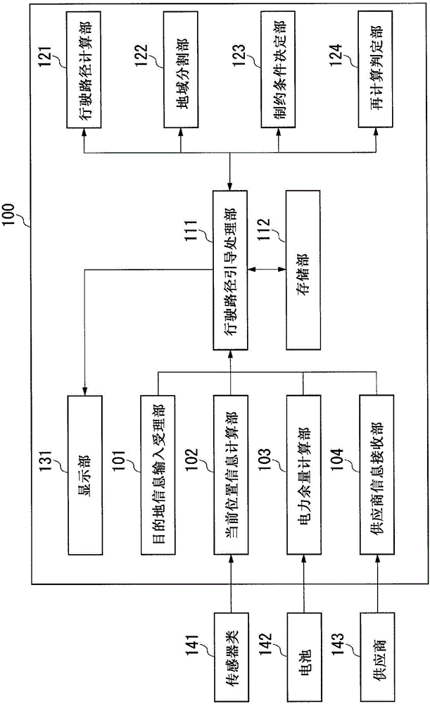
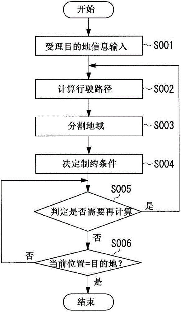
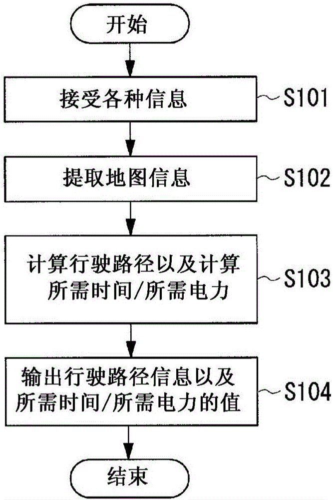
[0049] Below, refer to Figure 1 to Figure 6 , and the first embodiment of the present invention will be described.
[0050] figure 1 It is a figure which shows the whole structure of the travel route guidance apparatus of 1st Embodiment in this invention. The travel route guidance device 100 includes a destination information input accepting unit 101, a current position information calculation unit 102, a power remaining calculation unit 103, a supplier information receiving unit 104, a travel route guidance processing unit 111, a storage unit 112, and a travel route calculation unit. 121 , a region segmentation unit 122 , a constraint determination unit 123 , a recalculation determination unit 124 , and a display unit 131 .
[0051] In addition, the travel route guidance device 100 is connected to sensors 141 , a battery 142 , and a supplier 143 .
[0052] In addition, the travel route guidance device 100 is a device included in an in-vehicle device installed in a vehicle...
no. 2 Embodiment approach
[0114] Next, refer to Figure 7 to Figure 8 , and a second embodiment of the travel route guidance device of the present invention will be described. In addition, in this embodiment, the difference from the said 1st Embodiment is mainly described, and the description about the same part is abbreviate|omitted.
[0115] The travel route guidance device 100 of the present embodiment differs from the first embodiment in the operations of the area division unit 122 and the constraint condition determination unit 123 .
[0116] refer to Figure 7 , 8 , the operation of the region division unit 122 in this embodiment will be described.
[0117] Figure 7 This is an operation flowchart of the area dividing unit 122 in this embodiment. Figure 8 It is a diagram showing local area information in this embodiment.
[0118] First, the area segmentation unit 122 receives the travel route information output from the travel route calculation unit 121 from the travel route guidance process...
no. 3 Embodiment approach
[0133] Next, as a third embodiment, refer to Figure 9 , Figure 10 The driving route guidance system of the present invention will be described. In addition, in this embodiment, the difference from the said 1st Embodiment is mainly described, and the description about the same part is abbreviate|omitted.
[0134] The driving route guidance system 200 of the present embodiment is provided with the driving route guidance in the first embodiment in such a manner that the vehicle-mounted device 210 mounted on the electric vehicle and the management center device 220 for managing the operation of the electric vehicle are distributed and complement each other. The structure of the device 100 realizes the driving route guidance through cooperation of the vehicle-mounted device 210 and the management center device 220 .
[0135] Figure 9 It is a diagram showing the overall configuration of the travel route guidance system 200 . The driving route guidance system 200 includes an i...
PUM
 Abstract
Description
Claims
Application Information
 - R&D
- Intellectual Property
- Life Sciences
- Materials
- Tech Scout
- Unparalleled Data Quality
- Higher Quality Content
- 60% Fewer Hallucinations
Browse by: Latest US Patents, China's latest patents, Technical Efficacy Thesaurus, Application Domain, Technology Topic, Popular Technical Reports.
© 2025 PatSnap. All rights reserved.Legal|Privacy policy|Modern Slavery Act Transparency Statement|Sitemap|About US| Contact US: help@patsnap.com


