Control devices for internal combustion engines
A technology of a control device and an internal combustion engine, applied in engine control, electrical control, program control, etc., can solve problems such as low learning efficiency
- Summary
- Abstract
- Description
- Claims
- Application Information
AI Technical Summary
Problems solved by technology
Method used
Image
Examples
Embodiment approach 1
[0153] Structure of Embodiment 1
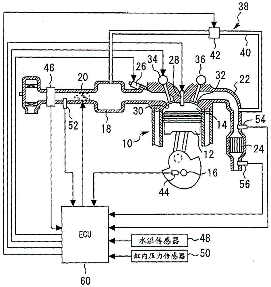
[0154] Below, refer to Figure 1 to Figure 4 Embodiment 1 of the present invention will be described. figure 1 It is an overall configuration diagram for explaining the system configuration of Embodiment 1 of the present invention. The system of the present embodiment includes a multi-cylinder engine 10 as an internal combustion engine. In addition, the present invention is applied to an internal combustion engine with any number of cylinders including single cylinder and multiple cylinders, figure 1 One cylinder among the multiple cylinders mounted in the engine 10 is shown as an example. in addition, figure 1 The shown system configurations represent all the configurations necessary for Embodiments 1 to 22 of the present invention, and only the configurations necessary for the system configurations may be used in each embodiment.
[0155] In each cylinder of the engine 10 , a combustion chamber 14 is formed by a piston 12 , and the pis...
Embodiment approach 2
[0198] Next, refer to Figure 5 Embodiment 2 of the present invention will be described. This embodiment has the same configuration as the above-mentioned first embodiment, and is characterized in that a linear function is used as the weight setting means. In addition, in this embodiment, the same reference numerals as in Embodiment 1 are assigned to the same components as in Embodiment 1, and description thereof will be omitted.
[0199]Features of Embodiment 2
[0200] Figure 5 It is a characteristic line diagram which shows the reduction characteristic of the weight value obtained from the linear function in Embodiment 2 of this invention. As shown in the figure, in this embodiment, a linear function in which the weight decreases in proportion to the distance from the reference position is used as the weight setting means. Also in this embodiment configured in this way, substantially the same effects as those in the first embodiment described above can be obtained. In...
Embodiment approach 3
[0202] Next, refer to Figure 6 Embodiment 3 of the present invention will be described. The present embodiment has the same configuration as the first embodiment described above, and is characterized in that a trigonometric function is used as the weight setting means. In addition, in this embodiment, the same reference numerals as in Embodiment 1 are attached to the same components as in Embodiment 1, and description thereof will be omitted.
[0203] Features of Embodiment 3
[0204] Figure 6 It is a characteristic line diagram which shows the reduction characteristic of the weight obtained by the trigonometric function in Embodiment 3 of this invention. As shown in the figure, in this embodiment, as the weight setting means, a trigonometric function in which the weight decreases in a sinusoidal manner according to the distance from the reference position is used. In the present embodiment configured in this way, substantially the same effects as those of the first embo...
PUM
 Abstract
Description
Claims
Application Information
 - R&D
- Intellectual Property
- Life Sciences
- Materials
- Tech Scout
- Unparalleled Data Quality
- Higher Quality Content
- 60% Fewer Hallucinations
Browse by: Latest US Patents, China's latest patents, Technical Efficacy Thesaurus, Application Domain, Technology Topic, Popular Technical Reports.
© 2025 PatSnap. All rights reserved.Legal|Privacy policy|Modern Slavery Act Transparency Statement|Sitemap|About US| Contact US: help@patsnap.com


