Optical film system optimization design method and product

An optimized design, optical film technology, applied in optics, optical components, complex mathematical operations, etc., can solve problems such as unoptimizable information, few reports on depolarization beam splitters, and complex mathematical polarization calculation, and achieve fast optimization speed Effect

Active Publication Date: 2020-01-14
HUAZHONG UNIV OF SCI & TECH
View PDF4 Cites 14 Cited by
  • Summary
  • Abstract
  • Description
  • Claims
  • Application Information

AI Technical Summary

Problems solved by technology

Although the Needle method and its improved method have the advantages of extremely fast calculation speed and global optimality compared with other synthesis methods, this method has two disadvantages: First, the process of calculating the position of the newly inserted thin layer of the film system needs to be complicated. Second, the state variable used in this method is equivalent admittance, which can only optimize the parameters related to reflection (reflectivity, reflection phase angle, etc.), but cannot optimize the information related to transmission
In conclusion, so far, there are few reports on depolarizing beam splitters that can achieve the depolarizing effect in both the amplitude and phase parameters at wide wavelengths and wide acceptance angles.

Method used


Image

  • Optical film system optimization design method and product
  • Optical film system optimization design method and product
  • Optical film system optimization design method and product

Examples


Embodiment 1

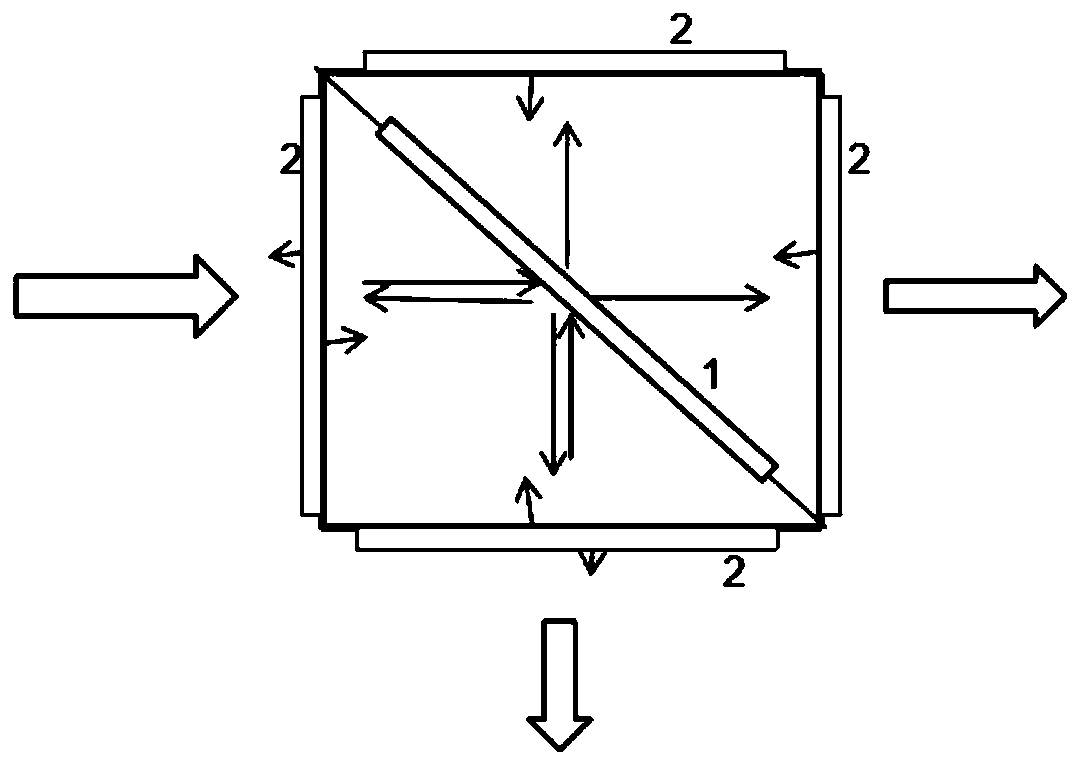
[0099] This embodiment relates to the design of the non-polarizing film system of the depolarized glued cubic beam splitter with wide band and wide acceptance angle. The structure of the beam splitter is as follows figure 2 As shown, the design of the non-polarizing film system of the beam splitter adopts a dielectric-metal scheme, and the materials used are all commonly used coating materials: TiO 2 , Al 2 o 3 , SiO 2 , Ag, specifically includes the following steps:

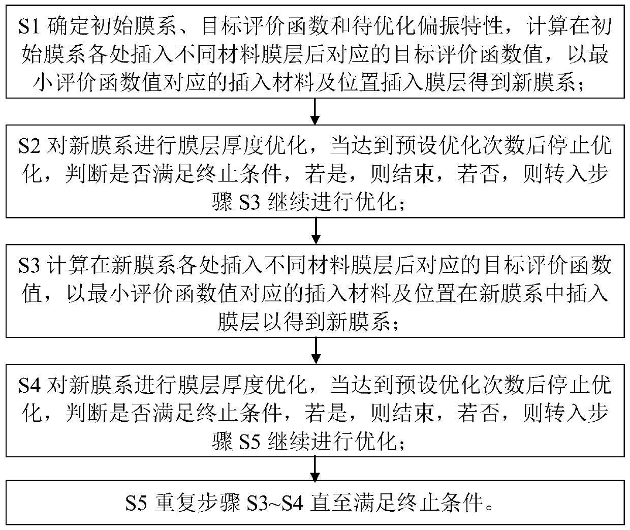
[0100] (1) Select material and design initial film system

[0101] Because the addition of a metal material film layer can flatten the polarization characteristic curve of a wide band, and it is easy to realize the design of wide acceptance angle change. Among them, Ag has the smallest polarization effect and better spectral neutrality in the visible light band, so the design material TiO 2 (marked as n 1 , whose optical constants refer to Figure 5 ), Al 2 o 3 (marked as n 2 , whose optical constants ...

Embodiment 2

[0120] This embodiment involves the design of the anti-reflection film system, which adopts an all-dielectric solution, and the materials used are all commonly used coating materials: TiO 2 , SiO 2 , MgF 2 , specifically including the following steps (basically consistent with the non-polarizing film design process):

[0121] (1) Select material and design initial film system

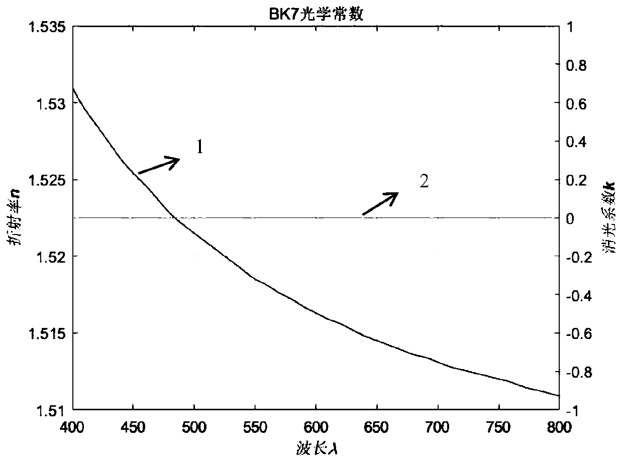
[0122] Select Design Material TiO 2 (marked as n 1 , whose optical constants refer to Figure 5 ), SiO 2 (marked as n 2 , whose optical constants refer to Figure 4 ), MgF 2 (marked as n 3 , whose optical constants refer to Figure 8 ), base BK7 (denoted as n 0 , whose optical constants refer to image 3 ), for the initial design, it is advisable to design a film system air|n with a two-layer film structure 1 ,n 3 n 0 , the physical thickness of the film layer is d n1 =20nm, d n3=20nm, the incident angle is 0°, and the incident medium is air (air);

[0123] (2) Setting design (optimiza...


PUM

PropertyMeasurementUnit
thicknessaaaaaaaaaa
thicknessaaaaaaaaaa
thicknessaaaaaaaaaa

Abstract

The invention belongs to the field of optical film system design, and relates to an optical film system optimization design method and a product. The method specifically comprises the following steps:firstly, calculating corresponding target evaluation function values after different material film layers are inserted into each part of an initial film system to insert a thin layer of the most suitable material into the most suitable position of the initial film system by using a cyclic traversal method; and optimizing the thickness of the newly obtained film system, and cyclically carrying outinsertion optimization process to optimize the obtained required film system. According to the invention, an unpolarized film system, an antireflection film system and a depolarization beam splittercan be designed and obtained; and compared with a current common Needle or an improvement method thereof, the method provided by the invention can optimize both a reflection polarization characteristic target and a transmission polarization characteristic target, and the optimization speed is extremely high under a certain condition.

Description

technical field [0001] The invention belongs to the field of optical film system design, and more specifically relates to an optical film system optimization design method and product. Background technique [0002] The calculation of the spectral characteristics of an optical film system usually adopts the method of calculating its characteristic admittance matrix (Tang Jinfa, Gu Peifu. Thin Film Optics and Technology. Beijing: Mechanical Industry Press, 1989), for a given incident angle, incident wavelength and incident / Exit medium, as long as the material (optical constant) and geometric thickness of each layer of the film system are given, the spectral characteristics of the film system can be easily calculated. The optical film system optimization design problem is the inverse problem of the above calculation, that is, the film system composition that can achieve this goal is reversely calculated according to the predetermined spectral characteristics. Due to the limit...

Claims


Application Information

Patent Timeline
Patent Type & Authority Applications(China)
IPC IPC(8): G02B27/00G02B1/115G02B5/00G06F17/16G06F30/17
CPCG02B1/115G02B5/00G02B27/0012G06F17/16
Inventor 陈修国郭恒琳刘世元陈超
Owner HUAZHONG UNIV OF SCI & TECH
Why Eureka
Try Eureka