Method for eliminating zero error
A zero-position error and zero-position technology, which is applied in the field of eliminating zero-position error, can solve problems such as the increase of zero-position error, the inability to automatically replace work rolls, and the inability of the moving block to accurately move to zero position, etc.
- Summary
- Abstract
- Description
- Claims
- Application Information
AI Technical Summary
Problems solved by technology
Method used
Image
Examples
Embodiment 1
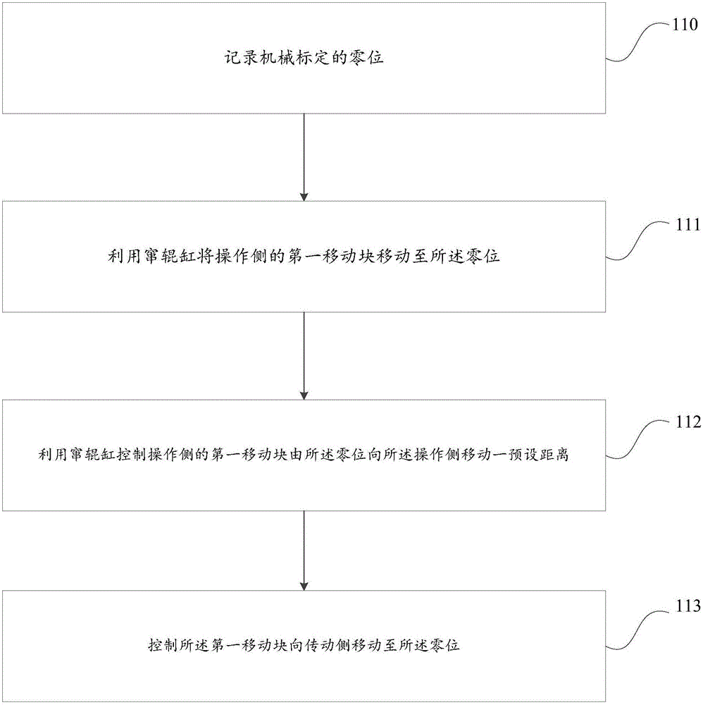
[0029] This embodiment provides a method for eliminating zero error, such as figure 1 As shown, the method mainly includes the following steps:
[0030] Step 110, record the zero position of mechanical calibration.
[0031] In this step, the zero position should be calibrated mechanically; specifically, firstly, the finishing mill should be controlled to stop and be in the state of replacing work rolls; secondly, the zero position should be set according to the requirements of the steel rolling process and the size of the equipment, that is, the zero position should be mechanically calibrated. Specifically, when the finishing mill stops and is in the state of replacing work rolls, the work rolls are pulled out, and the second moving block on the transmission side is sequentially moved to the zero position by using a jack. Manually operate the roll shifting cylinder in sequence to move the first moving block on the operating side from the zero position to the operating side fo...
Embodiment 2
[0043] In this embodiment, a hot rolling production line is taken as an example. When using the method provided in Embodiment 1 to replace work rolls, the details are as follows:
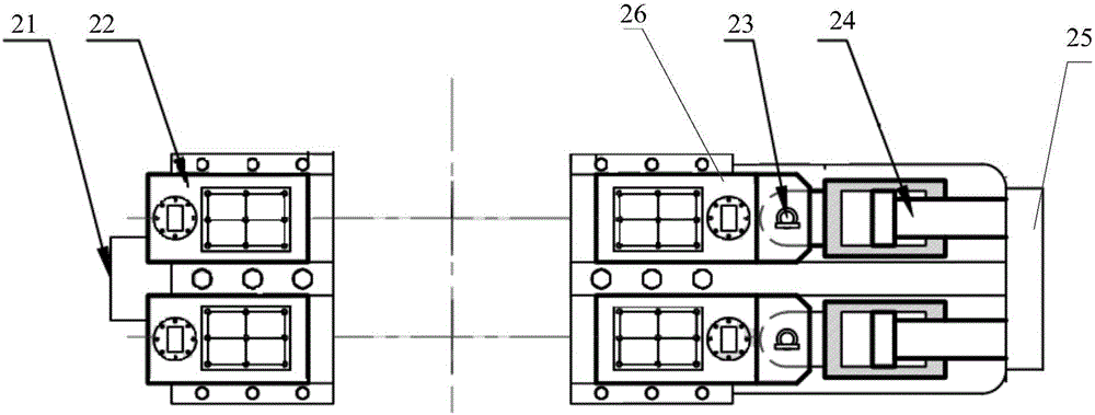
[0044] The hot rolling production line equipment provided in this embodiment is as figure 2As shown, the hot rolling production line equipment includes: transmission side fixed block 21, transmission side moving block 22, connecting pin 23, roll shifting cylinder 24, operation side fixed block 25 and operation side moving block 26; wherein, the transmission The transmission side clamp cylinder is arranged in the side moving block 22 , and the operation side clamp cylinder is arranged in the operation side moving block 26 .
[0045] When in the production process, the bearing seat at one end of the first work roll is connected with the first clamping plate of the transmission side clamping cylinder, and the bearing seat at the other end of the working roll is connected with the second clamping plate...
Embodiment 3
[0054] In this embodiment, when the preset distance is set to 20mm, the experiment is carried out using the method provided in Embodiment 1, and the specific steps are as follows:
[0055] Such as figure 2 As shown, the hot rolling production line equipment includes: transmission side fixed block 21, transmission side moving block 22, connecting pin 23, roll shifting cylinder 24, operation side fixed block 25 and operation side moving block 26; wherein, the transmission The transmission side clamp cylinder is arranged in the side moving block 22 , and the operation side clamp cylinder is arranged in the operation side moving block 26 .
[0056] When in the production process, the bearing seat at one end of the first work roll is connected with the first clamping plate of the transmission side clamping cylinder, and the bearing seat at the other end of the working roll is connected with the second clamping plate of the operation side clamping cylinder, Rolled steel. When the...
PUM
 Abstract
Description
Claims
Application Information
 - R&D
- Intellectual Property
- Life Sciences
- Materials
- Tech Scout
- Unparalleled Data Quality
- Higher Quality Content
- 60% Fewer Hallucinations
Browse by: Latest US Patents, China's latest patents, Technical Efficacy Thesaurus, Application Domain, Technology Topic, Popular Technical Reports.
© 2025 PatSnap. All rights reserved.Legal|Privacy policy|Modern Slavery Act Transparency Statement|Sitemap|About US| Contact US: help@patsnap.com


