A Calibration System of High Precision Laser Scanning Mirror Position Sensor

A laser scanning galvanometer and calibration system technology, which is applied in the field of high-precision laser scanning galvanometer position sensor calibration systems, can solve the problems of lack of, difficult to achieve scanning galvanometer position sensor calibration, etc., to achieve precise positioning and continuous rotation, reduce The effect of small measurement error and elimination of installation deviation

Active Publication Date: 2020-05-19
北京北航天宇长鹰无人机科技有限公司
View PDF18 Cites 0 Cited by
  • Summary
  • Abstract
  • Description
  • Claims
  • Application Information

AI Technical Summary

Problems solved by technology

The difficulty lies in: (1) the accuracy of the angular position sensor with the highest detection accuracy is in the same order of magnitude as that of the scanning galvanometer position sensor, and it is difficult to calibrate the scanning galvanometer position sensor; (2) there is still a lack of dedicated laser scanning galvanometer Rotary stage capable of producing microradian accuracy levels

Method used


Image

  • A Calibration System of High Precision Laser Scanning Mirror Position Sensor
  • A Calibration System of High Precision Laser Scanning Mirror Position Sensor
  • A Calibration System of High Precision Laser Scanning Mirror Position Sensor

Examples


Embodiment Construction

[0051] The technical scheme of the present invention will be described in detail below in conjunction with the accompanying drawings.

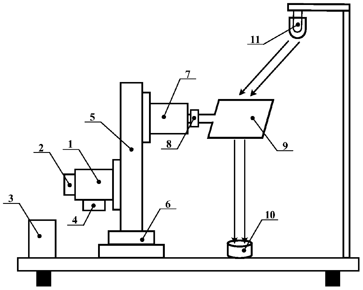
[0052] figure 1 It is a high-precision laser scanning galvanometer position sensor calibration system of the present invention, which consists of a permanent magnet synchronous motor 1 with low torque pulsation, a high-precision angular position sensor 2, a computer control system 3, a permanent magnet synchronous motor driver 4, and a reducer 5 , a zeroing mechanism 6, a calibrated galvanometer motor 7, a calibrated galvanometer 9, a calibrated angular position sensor 8, a laser source 11 and a photoelectric position detector 10.

[0053] Among them, the permanent magnet synchronous motor 1 with low torque ripple adopts a surface-mounted three-phase permanent magnet synchronous motor with 22 poles and 24 slots. thermal stability.

[0054] Among them, the high-precision angular position sensor 2 adopts the 17-bit absolute photoelectric senso...


PUM


Abstract

Provided in the invention is a high-precision laser scanning galvanometer position sensor calibration system comprising a low-torque-pulsating permanent-magnet synchronous motor, a high precision angular position sensor, a computer control system, a permanent-magnet synchronous motor driver, a speed reducer, a zero adjustment mechanism, a calibrated galvanometer motor, a calibrated galvanometer, acalibrated angular position sensor, a laser source, and a photoelectric position detector. The low-torque-pulsating permanent-magnet synchronous motor drives the calibrated galvanometer motor to makerotate by the speed reducer; and thus the motor corner motion at the milliradian precision level is transformed into the corner at a microradian precision level by using the speed reducer. Light generated by the laser source is reflected by the galvanometer and then the reflected light irradiates the photoelectric position detector; a corner signal of the galvanometer is transformed into a lightspot position signal at the photoelectric position detector, and the corner of the galvanometer is calculated by detecting the light spot displacement at the photoelectric position detector, so that the signal is used as a reference signal of the calibrated angular position sensor to complete the calibration of the calibrated angular position sensor. On the basis of the novel design of the calibrated system structure, the key part, and especially the test method, the designed calibration system can drive the calibrated galvanometer to make microradian corner movement and the corner measurementand calibration of the microradian precision level, thereby providing the foundation for the research and production of the high-precision laser marking system. The high-precision laser scanning galvanometer position sensor calibration system is suitable for the high-precision laser marking field.

Description

technical field [0001] The invention belongs to the technical field of laser marking processing, and in particular relates to a high-precision laser scanning vibrating mirror position sensor calibration system. Background technique [0002] Laser marking is a special processing technology that uses high-energy-density laser beams to interact with the surface of the object to be marked to form desired marks on the surface of the object to be marked. Compared with traditional screen printing, chemical corrosion, mechanical engraving and EDM processing techniques, laser marking technology has the advantages of fast marking speed, high marking accuracy, wide application of materials, low maintenance cost, no consumables, and no pollution And other advantages, gradually become an important development direction in the field of modern marking processing. [0003] The current laser marking system is mainly composed of a laser generator, a limited-angle motor, a galvanometer, and a...

Claims


Application Information

Patent Timeline
Patent Type & Authority Patents(China)
IPC IPC(8): G01B11/00
Inventor 徐金全秦文渊方豪郭宏
Owner 北京北航天宇长鹰无人机科技有限公司
Why Eureka
Try Eureka