A Method to Eliminate Zero Position Error

A zero-position error and zero-position technology, which is applied in the field of eliminating zero-position error, can solve problems such as the increase of zero-position error, the inability to automatically replace work rolls, and the inability of the moving block to accurately move to zero position, etc.

Active Publication Date: 2017-08-08
SHOUGANG JINGTANG IRON & STEEL CO LTD
View PDF7 Cites 0 Cited by
  • Summary
  • Abstract
  • Description
  • Claims
  • Application Information

AI Technical Summary

Problems solved by technology

[0006] Aiming at the problems existing in the prior art, the embodiment of the present invention provides a method for eliminating the zero position error, which is used to solve the problem that in the prior art, when the work roll is replaced, the moving block cannot be accurate due to the increased zero position error of the roll shifting system. Moved to the zero position, causing the clamping cylinder to be closed, and the technical problem that the work roll cannot be replaced automatically

Method used


Image

  • A Method to Eliminate Zero Position Error
  • A Method to Eliminate Zero Position Error

Examples


Embodiment 1

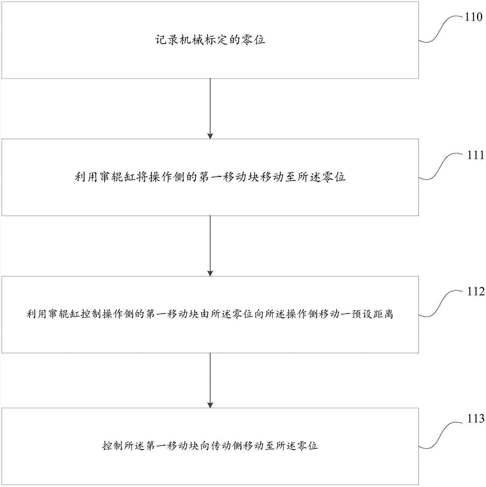
[0029] This embodiment provides a method for eliminating zero error, such as figure 1 As shown, the method mainly includes the following steps:

[0030] Step 110, record the zero position of mechanical calibration.

[0031] In this step, the zero position should be calibrated mechanically; specifically, firstly, the finishing mill should be controlled to stop and be in the state of replacing work rolls; secondly, the zero position should be set according to the requirements of the steel rolling process and the size of the equipment, that is, the zero position should be mechanically calibrated. Specifically, when the finishing mill stops and is in the state of replacing work rolls, the work rolls are pulled out, and the second moving block on the transmission side is sequentially moved to the zero position by using a jack. Manually operate the roll shifting cylinder in sequence to move the first moving block on the operating side from the zero position to the operating side fo...

Embodiment 2

[0043] In this embodiment, a hot rolling production line is taken as an example. When using the method provided in Embodiment 1 to replace work rolls, the details are as follows:

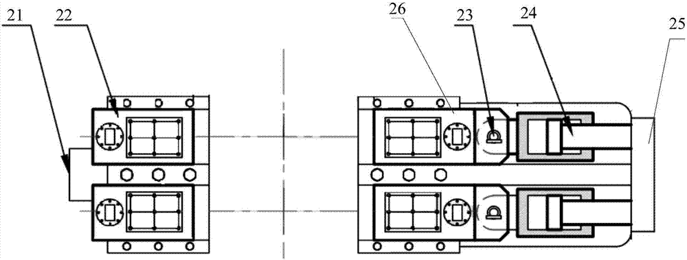
[0044] The hot rolling production line equipment provided in this embodiment is as figure 2As shown, the hot rolling production line equipment includes: transmission side fixed block 21, transmission side moving block 22, connecting pin 23, roll shifting cylinder 24, operation side fixed block 25 and operation side moving block 26; wherein, the transmission The transmission side clamp cylinder is arranged in the side moving block 22 , and the operation side clamp cylinder is arranged in the operation side moving block 26 .

[0045] When in the production process, the bearing seat at one end of the first work roll is connected with the first clamping plate of the transmission side clamping cylinder, and the bearing seat at the other end of the working roll is connected with the second clamping plate...

Embodiment 3

[0054] In this embodiment, when the preset distance is set to 20mm, the experiment is carried out using the method provided in Embodiment 1, and the specific steps are as follows:

[0055] Such as figure 2 As shown, the hot rolling production line equipment includes: transmission side fixed block 21, transmission side moving block 22, connecting pin 23, roll shifting cylinder 24, operation side fixed block 25 and operation side moving block 26; wherein, the transmission The transmission side clamp cylinder is arranged in the side moving block 22 , and the operation side clamp cylinder is arranged in the operation side moving block 26 .

[0056] When in the production process, the bearing seat at one end of the first work roll is connected with the first clamping plate of the transmission side clamping cylinder, and the bearing seat at the other end of the working roll is connected with the second clamping plate of the operation side clamping cylinder, Rolled steel. When the...


PUM


Abstract

The invention provides a method for eliminating a zero error. The method comprises the steps that the zero position calibrated mechanically is recorded; the relative position between a magnetic ring and a magnetic ruler of each channeling roll cylinder is set to be zero; first moving blocks on an operation side are controlled by the channeling roll cylinders to move to the zero position; the first moving blocks are controlled by the channeling roll cylinders to move towards the operation side from the zero position by a preset distance; the first moving blocks are controlled to move towards a drive side to the zero position; and by means of the preset distance, it is ensured that the first moving blocks precisely move to the zero position. Thus, the zero error caused by accumulated gap values of all components can be eliminated, it is ensured that the first moving blocks and second moving blocks can precisely move to the zero position, it is ensured that clamping plate cylinders are in an opened state, a work roll can be replaced safely, rapidly and automatically, and then the roll replacement time is shortened, the work efficiency is improved, and manual operation accidents are avoided.

Description

technical field [0001] The invention belongs to the technical field of hot-rolled steel strips, and in particular relates to a method for eliminating zero error. Background technique [0002] In the production process of hot-rolled strip steel, it is often necessary to replace work rolls. In order to quickly and safely replace work rolls, it is necessary to calibrate the zero position. [0003] In the prior art, the calibration method for the zero position of the roll shifting system of the finishing mill is as follows: firstly, use a jack to move the four moving blocks on the transmission side to the zero position before loading the rolls; secondly, manually move the roll shifting cylinder to move the four moving blocks on the operating side The moving block moves to the zero position in turn; then record the zero value of mechanical calibration on the automatic roll changing program of the host computer, perform zero marking on the program, install work rolls, start the ma...

Claims


Application Information

Patent Timeline
Patent Type & Authority Patents(China)
IPC IPC(8): B21B31/08
CPCB21B31/08
Inventor 张维中姚会忠王顺理王震张建峰
Owner SHOUGANG JINGTANG IRON & STEEL CO LTD
Why Eureka
Try Eureka