Method for eliminating zero point error of differential measurement circuit and differential measurement circuit

A technology of differential measurement and zero point error, which is applied in the zero point error elimination method of differential measurement circuit and the field of differential measurement circuit, can solve problems such as measurement error, achieve the effect of eliminating zero point error and improving measurement accuracy

Active Publication Date: 2016-01-20
RIGOL
View PDF7 Cites 0 Cited by
  • Summary
  • Abstract
  • Description
  • Claims
  • Application Information

AI Technical Summary

Problems solved by technology

[0007] The input zero point of amplifier U1, U2 and ADC converter will drift with the influence of temperature, time, power supply voltage and other factors, and the zero point drift will be directly added to the measured signal to generate measurement error

Method used


Image

  • Method for eliminating zero point error of differential measurement circuit and differential measurement circuit
  • Method for eliminating zero point error of differential measurement circuit and differential measurement circuit
  • Method for eliminating zero point error of differential measurement circuit and differential measurement circuit

Examples


Embodiment 1

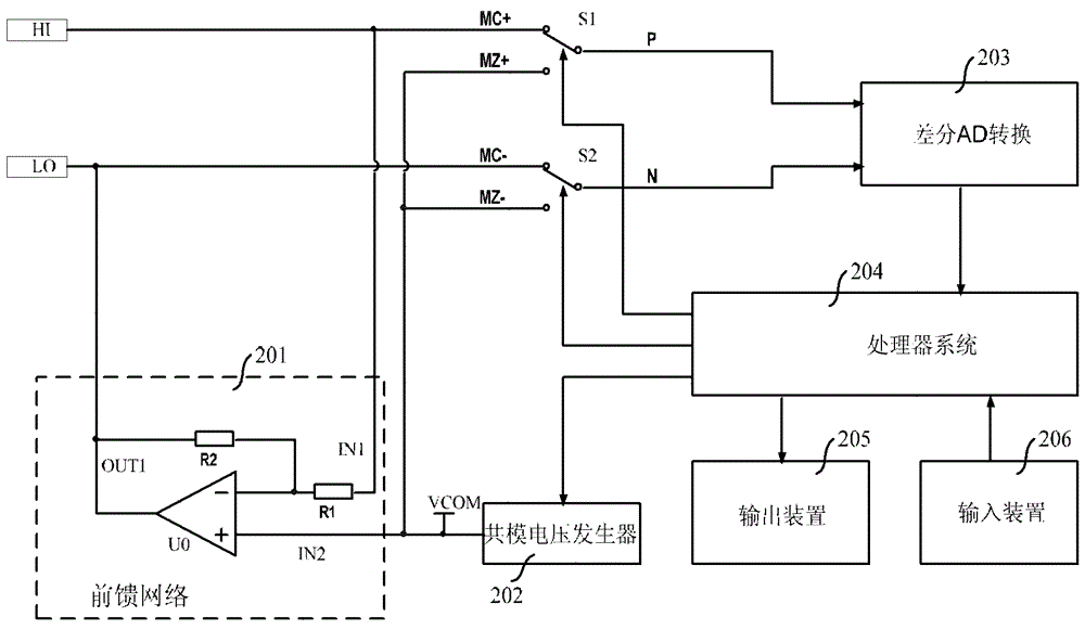
[0025] figure 2 It is a schematic diagram of the differential measurement circuit of the first embodiment of the present invention; as figure 2 As shown, the present invention provides a differential measurement circuit, which includes: a first input terminal HI, a second input terminal LO, a feedforward network 201, a common mode voltage generator 202, a first switch S1, a second switch S2, differential AD converter 203 and processor system 204;

[0026] The output terminal and the first input terminal IN1 of the feedforward network are respectively connected to the second input terminal LO and the first input terminal HI, and the second input terminal IN2 of the feedforward network is connected to the common mode voltage generator 202, The first input terminal HI is connected to the first input terminal of the differential AD converter 203 through the first switch S1, and the second input terminal LO is connected to the second input terminal of the differential AD convert...

Embodiment 2

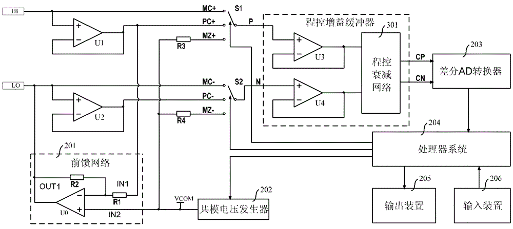
[0040] image 3 It is a schematic diagram of the differential measurement circuit of the first embodiment of the present invention; as image 3 As shown, the present invention provides a differential measurement circuit, which includes: a first input terminal HI, a second input terminal LO, a feedforward network 201, a common mode voltage generator 202, a first switch S1, a second A switch S2, a differential AD converter 203, a processor system 204, a first amplifier U1, a second amplifier U2, and a programmable gain buffer.

[0041] The output terminal of the feedforward network and the first input terminal IN1 are respectively connected to the second input terminal LO and the output terminal of the first amplifier U1, and the second input terminal IN2 of the feedforward network is connected to the common mode voltage generator 202, the programmable gain buffer is connected to the differential AD converter 203, the first input terminal HI is connected to the programmable gai...

Embodiment 3

[0066] Figure 4 It is a schematic diagram of the differential measurement circuit of the first embodiment of the present invention; as Figure 4 As shown, the present invention provides a differential measurement circuit. The differential measurement circuit includes: a first input terminal HI, a second input terminal LO, a feedforward network 201, a common mode voltage generator 202, a first A switch S1, a second switch S2, a third switch S3, a differential AD converter 203, a processor system 204, a first amplifier U1, a second amplifier U2, and a programmable gain buffer.

[0067] The output terminal OUT1 and the first input terminal IN1 of the feedforward network are respectively connected to the second input terminal LO and the output terminal of the first amplifier U1, and the second input terminal IN2 of the feedforward network is connected to the common mode voltage generator The programmable gain buffer is connected to the differential AD converter 203, the first in...


PUM


Abstract

The invention relates to a zero error elimination method of differential measurement circuit and differential measurement circuit; the differential measurement circuit comprises a first input terminal, a second input terminal, a feedforward network, a common mode voltage generator, a first switch, a second switch, a differential AD (Analog Digital) converter and a processor system; a common mode level of inputting the differential signal is controlled by the common mode voltage generator; the feedforward network is used for regulating the central levels of the first and second input terminals into the common mode level value; the differential AD converter is used for digital-to-analogue conversion of the signal and outputting the converted signal to the processor system; the processor system is used for controlling the first and second switches to be connected with the first and second input terminals respectively to measure the input differential signal, controlling the first and second switches to be connected with the common mode voltage generator to measure the zero error signal, and generating the data processing result according to the data output by the differential AD converter.

Description

technical field [0001] The invention relates to differential measurement circuit technology, in particular to a method for eliminating zero-point error of the differential measurement circuit and the differential measurement circuit. Background technique [0002] figure 1 It is a pre-differential amplifier in the prior art. The amplifier U1 forms a non-inverting input buffer to buffer and impedance transform the input signal of the terminal P; the amplifier U2 forms an inverting input buffer to buffer and impedance the input signal of the terminal N. transform. Resistors R6, R4, R3 and amplifier U3 form a feed-forward network for adjusting the midpoint of the input differential signal to a predetermined midpoint level. The reference voltage Vref, the resistor R1 and the resistor R2 form a differential output midpoint potential bias circuit. The double-pole single-throw switch K1 forms an input mode selection circuit. [0003] When the double-pole single-throw switch K1 i...

Claims


Application Information

Patent Timeline
Patent Type & Authority Patents(China)
IPC IPC(8): G01R19/25
Inventor 王悦王铁军李维森
Owner RIGOL
Why Eureka
Try Eureka