Double-layer brake disc molding device

A technology of forming device and brake disc, which is applied to casting forming equipment, core, casting mold, etc.

Active Publication Date: 2016-06-22
康迈(南京)机械有限公司
View PDF6 Cites 1 Cited by
  • Summary
  • Abstract
  • Description
  • Claims
  • Application Information

AI Technical Summary

Problems solved by technology

[0007] The purpose of the embodiments of the present invention is to provide a double-layer brake disc forming device, which can improve production efficiency and molding sand utilization on the basis of solving the difficult problem of sand falling

Method used


Image

  • Double-layer brake disc molding device
  • Double-layer brake disc molding device
  • Double-layer brake disc molding device

Examples


Embodiment Construction

[0035] In order to make the object, technical solution and advantages of the present invention clearer, the present invention will be further described in detail below in conjunction with the accompanying drawings and embodiments. It should be understood that the specific embodiments described here are only used to explain the present invention, not to limit the present invention.

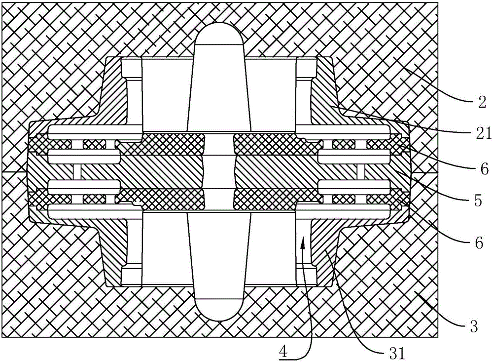
[0036] Such as Figure 2 to Figure 8 Commonly shown, a double-layer brake disc molding device includes an upper mold box 2 and a lower mold box 3, the upper mold box 2 is provided with an upper sand core 21, and the lower mold box 3 is provided with a lower sand core 31, The upper sand core 21 and the lower sand core 31 are mirror images, and an intermediate isolation core 5 is arranged between the upper sand core 21 and the lower sand core 31. Between the intermediate isolation core 5 and the upper sand core 21, and the intermediate isolation core 5 Between the lower sand core 31, an air duct for...


PUM


Abstract

The invention discloses a double-layer brake disc molding device which comprises an upper mold box and a lower mold box. An upper sand core is arranged in the upper mold box. A lower sand core is arranged in the lower mold box. A middle isolating core is arranged between the upper sand core and the lower sand core. An air channel molding core is arranged between the middle isolating core and the upper sand core. An air channel molding core is arranged between the middle isolating core and the lower sand core. Multiple through holes are formed in each air channel molding core. Molding cavities are formed among the upper sand core, the lower sand core, the air channel molding cores and the middle isolating core. The molding cavity in the lower sand core communicates with a casting system. Communicating channels communicating with the two molding cavities are formed in the middle isolating core. By the adoption of the double-layer brake disc molding, double-layer casting is achieved; within the same period, the molding number of brake discs is doubled, and production efficiency is improved; and meanwhile, the space of the upper mold box is utilized, so that during casting, the use amount of the sand is lowered greatly, the utilization rate of the sand in a sand bin is increased, the sand adhering to the brake discs is reduced, and thus a foundation can be conveniently established for shakeout on a shakeout machine.

Description

technical field [0001] The invention relates to a double-layer brake disk molding device. Background technique [0002] Present stage, automobile has been a kind of common tool of common family, and wherein brake disc 1 is an important part on the automobile, and its structure is (referring to figure 1 ): including an inner disc 14 and an outer disc 13, the inner disc 14 and the outer disc 13 are connected together by connecting ribs 12, and an air duct 11 is formed between adjacent connecting ribs 12, so as to dissipate the heat generated on the brake disc during braking in time. [0003] As we all know, the brake disc 1 is cast in the sand box (or mold box). At present, one brake disc 1 is molded in the height direction of the sand box, and two or three are formed in the length direction of the sand box. It is only formed in the lower sand box (or lower mold box), and the space of the upper sand box (or upper mold box) is wasted. There are following defects in this method...

Claims


Application Information

Patent Timeline
Patent Type & Authority Applications(China)
IPC IPC(8): B22C9/10B22C9/02B22C9/24
CPCB22C9/02B22C9/103B22C9/106B22C9/24
Inventor 袁超韩维波刘玉宝巨勐利黄晓刚陈宏志康小琴
Owner 康迈(南京)机械有限公司
Why Eureka
Try Eureka