Supercharge Your Innovation With Domain-Expert AI Agents!

Machining method for hollow discontinuous deep hole with inclined workblank face

A processing method and blank surface technology, which is applied in the field of deep hole processing in hollow spaces, can solve problems such as the lack of versatility of the processing method, limited clamping, and inability to guarantee the positional accuracy requirements, so as to reduce the probability of breaking the drill bit, The effect of eliminating position deviation and eliminating adverse effects

Active Publication Date: 2016-06-22
CHONGQING JIANGJIN SHIPBUILDING IND
View PDF5 Cites 2 Cited by
  • Summary
  • Abstract
  • Description
  • Claims
  • Application Information

AI Technical Summary

Problems solved by technology

[0004] 2. Since the hole of the bearing shell is a deep hole (the ratio of the length of the hole to the diameter of the hole is greater than 10), it is hollow, and there is an inclined blank surface at the hollow position, which makes its processing more difficult. If it is drilled from two directions, Then it will be unable to process due to the limitations of the workpiece and the machine table, and the clamping will also be limited, resulting in the non-versatility of the processing method;
[0006] 4. The traditional processing method used in the method of pre-processing similar holes has poor processing quality, cannot guarantee the positional requirements, and has low efficiency, and requires additional costs to customize non-standard tools, which is costly

Method used


Image

  • Machining method for hollow discontinuous deep hole with inclined workblank face
  • Machining method for hollow discontinuous deep hole with inclined workblank face
  • Machining method for hollow discontinuous deep hole with inclined workblank face

Examples


Embodiment Construction

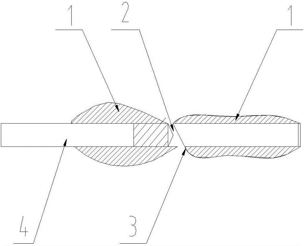
[0033] see Figure 1 to Figure 4 , is a preferred embodiment of the processing method of the hollow interrupted deep hole with an inclined blank surface. In this embodiment, the processing method is used to process the hollow interrupted deep hole of the bearing shell. The hollow interrupted deep hole includes two processing hole sections, and a hollow section between the two processing hole sections. The opposite orifice end faces of the two processing hole sections are oblique blank surfaces, and the desired machining diameter of the two processing hole sections is D21, the method is carried out in the following steps:

[0034] Step 1, select the outer end of the shorter processed hole segment among the two processed hole segments as the processing entry end of the hollow spaced deep hole, and use an end mill to mill and flatten the hole end face of the entry end so that the hole end face is vertical Interrupt the deep hole in the hollow;

[0035] Step 2, see figure 1 , c...


PUM


Abstract

The invention discloses a machining method for a hollow discontinuous deep hole with an inclined workblank face. By means of the method, the machining cost is lower, and machining accuracy is higher. The to-be-machined diameter of two machining hole segments is set to be D. The method includes the steps that firstly, one end of the hollow discontinuous deep hole is selected as the machining input end, and the hole opening end face of the machining input end is milled and leveled; secondly, a drill bit with the diameter being D is selected and used, is dilled into the hollow discontinuous deep hole from the machining input end and stops till drilling of the machining hole segment of the machining input end is completed; thirdly, a keyseat cutter with the diameter being smaller than D is selected and used, penetrates the machining hole segment machined in the second step and stops till the inclined workblank face of the other machining hole segment is milled and leveled; fourthly, a vertical milling cutter with the diameter being D is selected and used, penetrates the machining hole segment machined in the second step and stops till the inclined workblank face of the other machining hole segment is milled and leveled; and fifthly, the drill bit with the diameter being D is selected and used, penetrates the machining hole segment machined in the second stop and stops till drilling of the other machining hole segment is completed, and machining of the whole hollow discontinuous deep hole is completed.

Description

technical field [0001] The invention belongs to the technical field of mechanical processing, and in particular relates to a processing method for a hollow interrupted deep hole with an oblique blank surface. Background technique [0002] In recent years, with the continuous update of energy-saving products and the continuous shortage of energy, various enterprises have shifted towards saving materials, and the complexity of product parts produced will become higher and higher, resulting in an invisible increase in the processing difficulty of many products. big. Under the current awareness of reducing costs and creating benefits, reducing production costs has become the top priority of enterprises. Therefore, solving more and more complex problems at a lower cost has become the pursuit goal of many enterprises. The bearing shell is a key component in the power booster system, mainly reflected in the following aspects: [0003] 1. The bearing shell is a key part in the po...

Claims


Application Information

Patent Timeline
Patent Type & Authority Applications(China)
IPC IPC(8): B23B35/00B23B41/02
CPCB23B35/00B23B41/02B23B2260/0485
Inventor 鲁建于
Owner CHONGQING JIANGJIN SHIPBUILDING IND
Features
  • R&D
  • Intellectual Property
  • Life Sciences
  • Materials
  • Tech Scout
  • Unparalleled Data Quality
  • Higher Quality Content
  • 60% Fewer Hallucinations
Learn More