Clamping device of eight-station cold heading machine

A cold heading machine, eight-station technology, applied in the direction of conveyor objects, transportation and packaging, can solve the problems of billet feeding, lubricating oil splashing, polluting the working environment, etc., to solve the problem of material clamping, reduce mold loss, The effect of a high degree of automation

Active Publication Date: 2016-06-22
浙江东雄机床有限公司
View PDF8 Cites 2 Cited by
  • Summary
  • Abstract
  • Description
  • Claims
  • Application Information

AI Technical Summary

Problems solved by technology

[0002]Cold heading machine is one of the common fastener production equipment in modern industry. The traditional cold heading machine has a complex clamping device structure, difficult adjustment, and incorrect clamping. Stable, when the machine is working at high speed, the lateral force is relatively large, the up and down impacts are frequent, and it is easy to break, which directly leads to the damage of the mold; at the same time, these clamping devices are easy to cause lubricating oil to splash when working, which not only causes waste, but also pollutes working environment
In addition, whether the clamping device of the cold heading machine in the prior art can accurately transfer the blank from the previous stroke to the next stroke mainly depends on the gap between the parts in the mechanism. If the gap is too large, the manipulator will not be able to accurately send the blank to the center of the next main mold due to poor concentricity, resulting in many uncertain factors in the production process

Method used


Image

  • Clamping device of eight-station cold heading machine
  • Clamping device of eight-station cold heading machine
  • Clamping device of eight-station cold heading machine

Examples


Embodiment Construction

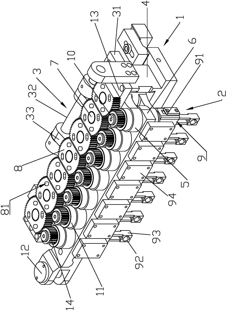
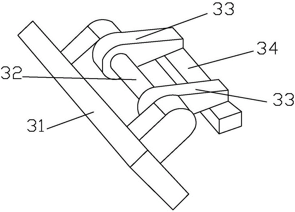
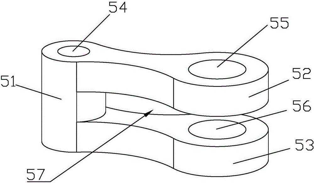
[0034] like Figure 1 to Figure 6 As shown, the clamping device of the eight-station cold heading machine includes a clamping mechanism 1 and a sandwich mechanism 2, and the clamping mechanism 1 is connected to the sandwich mechanism 2. Clamping mechanism 1 includes clamping box 4, clamping connecting rod 6 and clamping swing rod 5, clamping connecting rod 6 is connected with clamping swing rod 5, clamping swing rod 5 is installed in clamping box 4, clamping table swings The bar 5 is connected with the clamping table swinging rod shaft 7, and the clamping table swinging rod shaft 7 is provided with a guide gear 8. The clamping box 4 wraps the clamping table connecting rod 6 and the clamping table swinging rod 5 inside to prevent the external harsh working environment from affecting the normal movement of the clamping table mechanism 1. The structure is simple and compact, which reduces the exposed parts of the equipment and saves materials. The sandwich mechanism 2 includes a...


PUM


Abstract

The invention discloses a clamping device of an eight-station cold heading machine. The clamping device comprises a clamping table mechanism and a clamping core mechanism, wherein the clamping table mechanism is connected with the clamping core mechanism, the clamping table mechanism comprises a clamp box, a clamping table connecting rod and a clamping table oscillating rod, the clamping table connecting rod is connected with the clamping table oscillating rod, the clamping table oscillating rod is installed in the clamp box, a clamping table oscillating rod shaft is connected to the clamping table oscillating rod, a guide gear is arranged on the clamping table oscillating rod shaft, the clamping core mechanism comprises a clamping core shaft and a clamping assembly, a rolling gear is arranged on the upper part of the clamping core shaft, the rolling gear is engaged with the guide gear, the clamping table connecting rod and the clamping table oscillating rod are connected to the middle of the clamping core shaft, and the clamping assembly is connected to the lower part of the clamping core shaft. The device has the advantages of simple and compact structure, high degree of automation, stable working performance and high production efficiency, both the clamping table connecting rod and the clamping table oscillating rod are wrapped in the clamp box, so that the normal movement of the clamping table mechanism is not influenced by the outside adverse working environment, and the exposed part of equipment is reduced, so that materials are saved.

Description

technical field [0001] The invention relates to the field of cold heading machines, in particular to a clamping device for an eight-station cold heading machine. Background technique [0002] Cold heading machine is one of the common fastener production equipment in modern industry. The traditional cold heading machine has a complex structure of clamping device, difficult adjustment, unstable clamping, and large lateral force when the machine works at high speed. , frequent up and down impacts, easy to break, and directly lead to damage to the mold; at the same time, these clamping devices are likely to cause lubricating oil splashes during work, which not only causes waste, but also pollutes the working environment. In addition, whether the clamping device of the cold heading machine in the prior art can accurately transfer the blank from the previous stroke to the next stroke mainly depends on the gap between the parts in the mechanism. If the gap is too large, the manipu...

Claims


Application Information

Patent Timeline
Patent Type & Authority Applications(China)
IPC IPC(8): B65G47/90
CPCB65G47/902
Inventor 王春风成荣栋钱志勇袁磊
Owner 浙江东雄机床有限公司
Why Eureka
Try Eureka