Conveying platform with lifting structure
A lifting structure and platform technology, applied in the direction of transportation, packaging, loading/unloading, etc., can solve the problems of laborious loading and unloading of goods, and achieve the effects of improving efficiency, convenient movement, and convenient use
- Summary
- Abstract
- Description
- Claims
- Application Information
AI Technical Summary
Problems solved by technology
Method used
Image

Examples
Embodiment 1
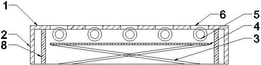
[0026] A platform with a lifting structure on the top surface, the platform includes a plane 1, a middle frame 2, a lifting system 3, a lifting surface 4, and a rolling member 5. The plane 1 and the middle frame 2 form a bottomless cubic structure with space inside, The lifting system 3 is fixed inside the cube, and the lifting system 3 is connected to the lifting surface 4, and the lifting surface 4 is provided with a rolling element 5, and the rolling element 5 is arranged between the lifting surface 4 and the plane 1 (ie, the top surface). between; the plane 1 (ie, the top surface) is provided with holes or grooves 6 through which the rolling elements 5 can pass. When the rolling member 5 is a roller, there is a long groove corresponding to the roller on the plane 1, and the roller can rise above the plane 1 through the long groove, so that the sliding friction between the goods and the plane becomes rolling friction. When the rolling member 5 is a plurality of universal b...
Embodiment 2
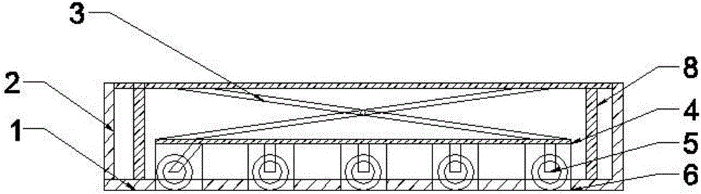
[0028] as attached figure 2 As shown, a platform with a lifting structure on the bottom surface includes two planes 1, a middle frame 2, a lifting system 3, a lifting surface 4, and rolling parts 5. The plane 1 and the middle frame 2 form a cubic structure with space inside. , the lifting system 3 is fixed inside the cube, and the lifting system 3 is connected to the lifting surface 4, the lifting surface 4 is provided with a rolling element 5, and the rolling element 5 is arranged between the lifting surface 4 and the bottom plane; The plane 1 is provided with holes capable of passing the rolling elements 5 . The rolling member 5 is a wheel, and the wheel includes universal wheels, and two universal wheels are located on the same side of the pallet, and the universal wheels are provided with a brake mechanism. The lifting system 3 is a screw lifting system. One side of the middle frame 2 is also provided with a dragging piece 7, and the dragging piece 7 is located on the s...
Embodiment 3
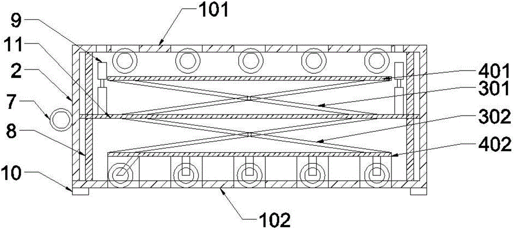
[0030] Platform with lifting mechanism on both sides, as attached image 3 As shown, the table top includes two planes (i.e., upper plane and lower plane), middle frame 2, lifting system 3, lifting surface 4, and rolling member 5. The plane and middle frame 2 form a cubic structure with space inside, so The lifting system 3 is fixed inside the cube, and the lifting system 3 is connected to the lifting surface 4, and the lifting surface 4 is provided with a rolling element 5, and the rolling element 5 is arranged between the lifting surface 4 and the plane 1; A hole that can pass through the rolling element 5 is arranged on the plane.
[0031] The lifting surface 4 includes an upper lifting surface 401 and a lower lifting surface 402, the lifting system 3 includes an upper lifting system 301 and a lower lifting system 302, the upper lifting surface 401 is connected to the upper lifting system 301, and the lower lifting system 3 The surface 402 is connected to the lower lifting...
PUM
 Abstract
Description
Claims
Application Information
 - R&D
- Intellectual Property
- Life Sciences
- Materials
- Tech Scout
- Unparalleled Data Quality
- Higher Quality Content
- 60% Fewer Hallucinations
Browse by: Latest US Patents, China's latest patents, Technical Efficacy Thesaurus, Application Domain, Technology Topic, Popular Technical Reports.
© 2025 PatSnap. All rights reserved.Legal|Privacy policy|Modern Slavery Act Transparency Statement|Sitemap|About US| Contact US: help@patsnap.com