Apparatus for multi-directional pressure-controlled spray seal pressure and pipe string containing same

A pressure control and nozzle technology, applied in the directions of sealing/isolation, production fluids, wellbore/well components, etc., to achieve the effect of reducing operating procedures, simplifying operating procedures, and reducing operating costs

Active Publication Date: 2018-06-12
CHINA PETROLEUM & CHEM CORP +1
12 Cites 0 Cited by

AI-Extracted Technical Summary

Problems solved by technology

[0004] Through the above method, although the stimulation of the reservoir can be complete...

Method used

[0046] According to the present invention, in the direction from top to bottom, a first step 45 and a second step 46 are provided on the inner wall of the lower end of the groove 44 of the inner cylinder 6. At the same time, a limiting member 47 is provided on the inner wall of the inner tube 6 at the lower end of the second step 46 . Preferably, the limiting member 47 may be a snap spring. Correspondingly, a retaining ring 48 is provided at the lower end of the groove 44, and the retaining ring 48 is configured in a cylindrical shape. Also, on an axially intermediate portion of the outer wall of the stop ring 48, a protruding ring 49 protruding radially outward is provided. The protruding ring 49 is interstitially arranged between the second step 46 and the stopper 47, so that the upper end surface of the stop ring 48 is opposite to the first step 45, and the lower end surface of the stop ring 48 extends beyond the lower end surface of the inner tube 6 . Meanwhile, a sealing member 51 is provided between the upper end surface of the retaining ring 48 and the first step 45 . Preferably, the sealing member 51 may be a rubber sleeve. Thus, put in the opener 40 and make the opener 40 move down together with the inner cylinder 6. When the stop ring 48 meets the inner cylinder seat 28, the inner cylinder 6 continues to move down, so that the sealing member 51 expands to raise the inner cylinder 6 and the inner cylinder 6. The seal between tools 40 is broken. Through this arrangement, the sealing performance...

Abstract

The invention provides a device used for multidirectional pressure control type spraying-sealing fracturing and a tubular column comprising the same. The device comprises a barrel-shaped upper connector, a nozzle sleeve, a central rod, a packer, a lower connector, an inner barrel, nozzles and an opening tool, wherein the nozzle sleeve is provided with circulating holes and pressure transmission holes, and the nozzles are arranged on the circulating holes; the inner barrel is arranged on the inner wall of the nozzle sleeve to seal the nozzles and the pressure transmission holes. After the opening tool is thrown in, under the action of pressure liquid, the inner barrel moves downwards to expose the nozzles and the pressure transmission holes, so that the packer is set, and then perforation can be carried out through the nozzles. The nozzles can fall off from the circulating holes so that subsequent fracturing operation can be carried out. By means of the device, the operation cost can be lowered, and the modification effect is improved.

Application Domain

Fluid removalSealing/packing

Technology Topic

Spray nozzleAerospace engineering +5

Image

  • Apparatus for multi-directional pressure-controlled spray seal pressure and pipe string containing same
  • Apparatus for multi-directional pressure-controlled spray seal pressure and pipe string containing same
  • Apparatus for multi-directional pressure-controlled spray seal pressure and pipe string containing same

Examples

  • Experimental program(1)

Example Embodiment

[0041] The present invention will be further described below in conjunction with the drawings.
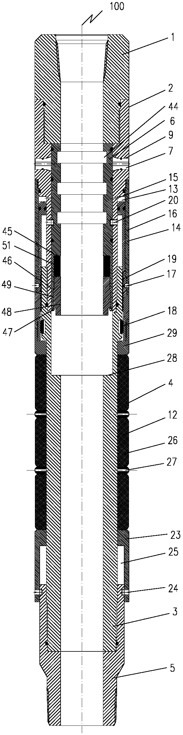
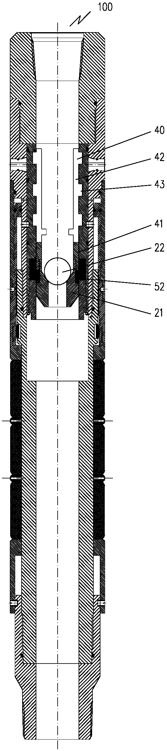
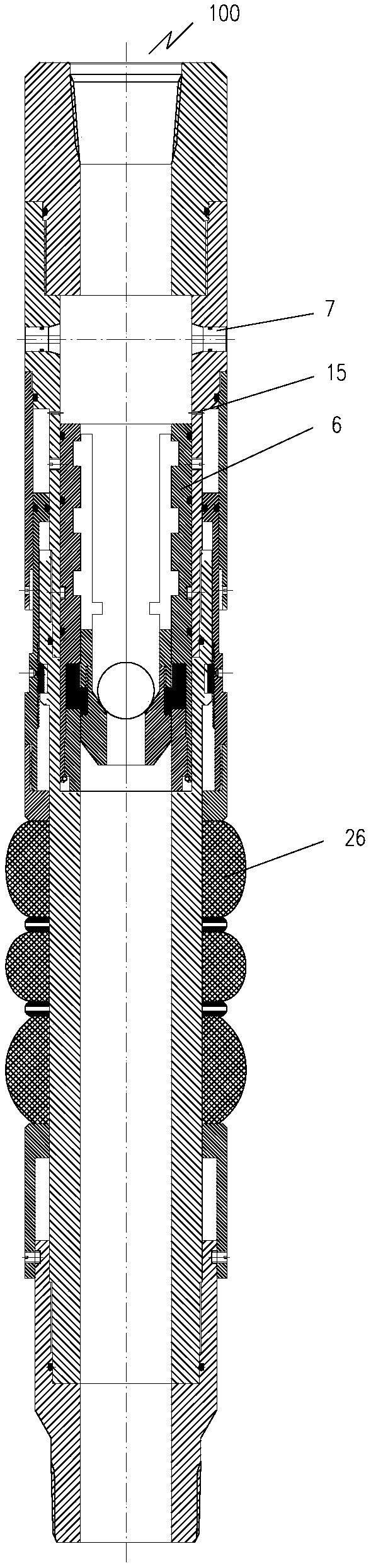
[0042] figure 1 A device 100 for multi-directional pressure-controlled spray seal pressure according to an embodiment of the present invention is shown. Such as figure 1 As shown, the device 100 includes an upper joint 1, a nozzle sleeve 2, a center rod 3, a packer 4, a lower joint 5, an inner cylinder 6, a nozzle 7 and an opening tool 40 (in figure 2 Shown in). Among them, the upper joint 1 is configured in a cylindrical shape and is used to connect with the oil pipe 8 to send the device 100 into the reservoir. The nozzle cover 2 is provided at the lower end of the upper joint 1 and is configured in a cylindrical shape. At the same time, the peripheral wall of the nozzle cover 2 is provided with a circulation hole 9 communicating with the inside and outside. The center rod 3 is arranged at the lower end of the nozzle sleeve 2 and has a cylindrical shape. The packer 4 is arranged on the outer wall of the lower end of the nozzle sleeve 2 and extends to the outer wall of the center rod 3 to be used for the annulus 11 between the device 100 and the casing 10. In addition, the packer 4 has a glue cylinder assembly 12 and a pressure transmission hole 15, and the pressure transmission hole 15 is arranged on the nozzle sleeve 2 and located at the lower end of the circulation hole 9, and the glue cylinder assembly 12 is arranged on the center rod 3. The lower joint 5 is provided at the lower end of the center rod 3 and is configured in a cylindrical shape. The inner cylinder 6 is arranged in the nozzle cover 2, and at the same time, the inner cylinder 6 is slidably connected with the nozzle cover 2 to ensure that the circulation hole 9 and the pressure transmission hole 15 are blocked or exposed. The nozzle 7 is confined at the flow hole 9 by the inner cylinder 6. After the perforation is completed, the nozzle 7 is configured to fall from the flow hole 9, thereby exposing the flow hole 9 and the pressure transmission hole 15 to activate the packer 4 and Prepare for subsequent fracturing operations. The opening tool 40 is selectively arranged in the inner cylinder 6 and cooperates with the inner cylinder 6 to drive the inner cylinder 6 to move down.
[0043] Therefore, after the pipe string 50 of the device 100 with this structure is lowered into the reservoir, the inner cavity of the inner cylinder 6 is closed by inserting the opening tool 40, and then the pressure liquid is injected into the pipe string 50, and the pressure Under the action of the liquid, the inner cylinder 6 moves relative to the nozzle sleeve 2 to expose the nozzle 7 and the pressure transmission hole 15, such as image 3 Shown. At the same time, the pressure fluid enters the packer 4 through the pressure transmission hole 15 and urges the packer 4 to set. Therefore, the sand-carrying liquid injected into the inner cylinder 6 can generate a high-speed jet through the nozzle 7 to enter the formation to complete the reservoir perforation. Such as Figure 4 As shown, after the perforation of the reservoir is completed, the nozzle 7 is caused to fall from the circulation hole 9, and the fracturing fluid can be injected into the pipe string 50 to complete the large displacement fracturing, such as Figure 5 Shown. Therefore, using the device 100 for multi-directional pressure control type spray sealing pressure, perforation and fracturing can be realized only by running the pipe string 50 once. Therefore, the device 100 for the multi-directional pressure control type spray seal pressure can reduce the operation process and reduce the operation cost. Furthermore, by using the device 100, after one operation of throwing and opening the tool 40, the packing, perforating and fracturing operations of the packer 4 can be completed, thereby further reducing the operating procedures and reducing the construction cost. At the same time, in the process of reforming the reservoir, since the fracturing is performed at the corresponding position after the perforation is completed, the device 100 can ensure the accuracy and precision of the fracturing, thereby improving the fracturing effect.
[0044] In one embodiment, such as figure 2 As shown, the opening tool 40 includes an opening tool main body 41, an elastic card 42, a ball seat 21 and a ball 22. The main body 41 of the opening tool is configured in a cylindrical shape for being arranged in the inner cylinder 6. The elastic card 42 is arranged at the upper end of the opening tool body 41. Preferably, there may be multiple elastic cards 42 and distributed along the circumferential direction. The ball seat 21 is provided at the lower end of the opening tool body 41 for placing the ball 22. A protrusion 43 is provided on the elastic card 42. Correspondingly, a groove 44 is provided on the inner cylinder 6 for mating with the protrusion 43. In the process of putting the opening tool 40 into the inner cylinder 6, when the opening tool 40 encounters the matching inner cylinder 6, the elastic card 42 expands outward, so that the protrusion 43 and the groove 44 are matched, so that the opening tool 40 is positioned On the inner cylinder 6. In this case, the internal circulation passage of the inner cylinder 6 is blocked, and at this time, the inner cylinder 6 can be driven to move downward by injecting pressure liquid. Through the cooperation of the opening tool 40 and the inner cylinder 6 of this structure, the lower movement of the inner cylinder 6 can be realized, which avoids the problem of incapability of full diameter and limited number of stages caused by the lowering of the inner cylinder 6 by throwing a ball. . That is, through this arrangement, the full diameter of the pipe string 50 is realized, and then the “innumerable” level fracturing construction is realized.
[0045] According to the present invention, an inner cylinder seat 28 is provided on the inner wall of the center rod 3 to limit the downward movement position of the inner cylinder 6. The inner cylinder seat 28 may be configured as a stepped platform structure.
[0046] According to the present invention, a first step 45 and a second step 46 are provided on the inner wall of the lower end of the groove 44 of the inner cylinder 6 in the direction from top to bottom. At the same time, a limit piece 47 is provided on the inner wall of the inner cylinder 6 at the lower end of the second step 46. Preferably, the limiting member 47 may be a circlip. Correspondingly, a retaining ring 48 is provided at the lower end of the groove 44, and the retaining ring 48 is configured in a cylindrical shape. In addition, a protruding ring 49 protruding radially outward is provided on the axial middle portion of the outer wall of the stop ring 48. The protruding ring 49 is intermittently arranged between the second step 46 and the limiting member 47, so that the upper end surface of the stop ring 48 is opposite to the first step 45, and the lower end surface of the stop ring 48 extends beyond the lower end surface of the inner cylinder 6. . At the same time, a seal 51 is provided between the upper end surface of the retaining ring 48 and the first step 45. Preferably, the sealing member 51 may be a rubber sleeve. As a result, the opening tool 40 is put in and the opening tool 40 and the inner cylinder 6 move down together. When the stop ring 48 is in line with the inner cylinder seat 28, the inner cylinder 6 continues to move down, causing the seal 51 to expand to increase the inner cylinder 6 and The seal between the tools 40 is opened. Through this arrangement, the sealing performance between the inner cylinder 6 and the opening tool 40 can be improved to ensure that the inner cylinder 6 can move down smoothly after the pressure fluid is injected.
[0047] According to the present invention, an elastic booster ring 52 is provided between the opening tool body 41 and the ball seat 21 in the axial direction. Preferably, the elastic boosting ring 52 may be a rubber tube. The provision of the elastic booster ring 52 reduces the gap between the opening tool 40 and the oil pipe 8 and the like. Thus, in the process of feeding the opening tool 40 by pressure, liquid leakage is reduced, so that the opening tool 40 can be fed more smoothly.
[0048] In one embodiment, in the direction from the inside to the outside, the cross-sectional area of ​​the flow hole 9 is reduced, while the shape of the nozzle 7 matches the flow hole 9. For example, the cross-section of the flow hole 9 may include figure 1 The trapezoid shown. When the nozzle 7 is under pressure from the inside to the outside, the nozzle 7 can be pressed at the position of the flow hole 9. When the nozzle 7 is under pressure from the outside to the inside, the nozzle 7 can be made to fall off from the flow hole 9. It should be noted that in the initial state, the nozzle 7 is limited by the inner cylinder 6 and will not fall off. Therefore, after the perforation is completed, pressure fluid can be injected into the annulus 11, so that the nozzle 7 is thrust and falls from the circulation hole 9, such as Figure 4 Shown.
[0049] In another embodiment, before fracturing, a liquid that can dissolve the nozzle 7 can also be injected into the tubing 8 or the annulus 11 to expose the flow hole 9.
[0050] Since it is necessary to perforate through the nozzle 7, the wear resistance of the nozzle 7 must be ensured. Under the precursor that guarantees the wear resistance of the nozzle 7, high cost is required to remove it by corrosion. Moreover, in the actual operation process, it may happen that the nozzle 7 is not completely corroded, or other parts of the device 100 are corroded. Therefore, in order to ensure the smooth progress of fracturing, a first circulation hole (not shown in the figure) is also provided on the nozzle sleeve 2, and a plug (not shown in the figure) that is easier to dissolve with a reagent is provided at the first circulation hole. Out) to ensure that the device 100 exposes the flow hole 9 and/or the first flow hole for fracturing. During the perforation process, the sand-carrying liquid can be injected into the formation through the nozzle 7. After the perforation is completed, a liquid that can dissolve the plug can be injected into the tubing 8 or the annulus 11 to expose the first flow hole to complete fracturing. Through this setting method, the pre-perforation operation is not affected, and the subsequent fracturing process is ensured. For example, the plug is made of aluminum-magnesium alloy material, and after the perforation is completed, an acid solution can be injected into the tubing 8 or the annulus 11 to dissolve the plug.
[0051] According to the present invention, the packer 4 further includes an outer cylinder 16, a piston cylinder 13 and a piston 14. Wherein, the upper end of the outer cylinder 16 is sleeved and fixedly connected to the outer wall of the nozzle sleeve 2, and the outer cylinder 16 extends downward and passes over the center rod 3. Thereby, the piston cylinder 13 is formed by the upper end surface of the center rod 3, the inner wall of the outer cylinder 16, and the nozzle sleeve 2. The upper end of the piston 14 is arranged in the piston cylinder 13, and the lower end of the piston 14 extends downward from between the central rod 3 and the outer cylinder 16 and abuts against the rubber cylinder assembly 12. At the same time, in the initial state, the piston 14 and the outer cylinder 16 are connected by the second shear pin 17. The pressure transmission hole 15 can communicate with the piston cylinder 13 to inject pressure fluid into the piston cylinder 13 through the pressure transmission hole 15. In addition, the pressure transmission hole 15 is located at the lower end of the circulation hole 9 and at the upper end of the upper surface of the piston 14 so that the piston 14 can receive the pressure fluid from the pressure transmission hole 15. In the initial state, the pressure transmission hole 15 is closed by the inner cylinder 6. In the process of injecting the pressure liquid, the inner cylinder 6 can move downward to expose the pressure transmission hole 15. At the same time, the pressure fluid enters the piston cylinder 13 and pushes the piston 14. Under the pressure, the second shear pin 17 is sheared, causing the piston 14 to move downward, and the downward piston 14 pushes the rubber cylinder assembly 12 to make the rubber cylinder The component 12 functions to seal the annulus 11.
[0052] In order to ensure the safety of the isolation, the glue cylinder assembly 12 includes a plurality of glue cylinders 26, and a spacer ring 27 is arranged between adjacent glue cylinders 26. For example, the glue cartridge assembly 12 includes three glue cartridges. This arrangement improves the packing effect of the packer 4, thereby ensuring the perforation and fracturing efficiency of the device 100.
[0053] In order to make the rubber cylinder 26 receive a uniform force, a push rod 29 is provided between the piston 14 and the rubber cylinder assembly 12 to transmit the force of the piston 14 to the rubber cylinder assembly 12. The upper end of the push rod 29 is fixedly connected to the piston 14, the lower end is slidably connected to the central rod 3, and the lower end surface abuts the rubber cylinder 26.
[0054] In order to prevent the glue cylinder assembly 12 from retreating, a first ratchet 18 is provided on the outer wall of the center rod 3. At the same time, a second ratchet tooth 19 is provided on the inner wall of the piston 14. During the downward movement of the piston 14, the second ratchet tooth 19 also moves downward. After the piston 14 moves to the position so that the rubber cylinder 26 expands and seals the annulus 11, the second ratchet tooth 19 and the first ratchet tooth 18 Match to prevent the glue cylinder assembly 12 from returning. Through this arrangement, the setting safety of the packer 4 can be ensured, thereby ensuring the subsequent perforation and fracturing operations.
[0055] According to the present invention, the inner cylinder 6 and the nozzle cover 2 are connected by the first shear pin 20. Therefore, in the process of blocking the inner cavity of the inner cylinder 6 and injecting pressure fluid into it, as the pressure increases, the first shear pin 20 is sheared, so that the inner cylinder 6 can be moved down to expose the nozzle 7 and the transmission. 压孔15. This structure is simple and easy to implement.
[0056] In a preferred embodiment, the device 100 further includes an unblocking stop ring 23 arranged at the lower end of the packer 4. The upper end of the unblocking stop ring 23 is sleeved on the outer wall of the center rod 3 and is slidably connected with the center rod 3. The upper end surface of the unblocking ring 23 abuts the rubber cylinder 26, and the lower end is fixedly connected to the lower joint 5 through the third shear pin 24. At the same time, the unblocking baffle ring 23 forms a first space 25 with the center rod 3 and the lower joint 5 to provide an escape space. When the packer 4 needs to be unpacked, the upper joint 1 can be lifted up. The center rod 3 and the lower joint 5 have a tendency to follow the upward movement of the upper joint 1. As the rubber cylinder 26 is in frictional contact with the annular space 11 The third shear pin 24 is sheared under the pulling force. After the third shear pin 24 is cut off, the unblocking stop ring 23 and the lower joint 5 move relative to each other, so that the expanded rubber cylinder 26 rebounds and the packer 4 is unpacked. Through this arrangement, the operating safety of the device 100 can be improved, so that the pipe string 50 can be lifted out of the casing 10 in an emergency.
[0057] The invention also relates to a pipe string 50. The pipe string 50 includes an oil pipe 8 and a device 100 fixedly connected to the oil pipe 8, such as Figure 5 Shown. In order to increase the scale of reservoir reconstruction and improve work efficiency. A plurality of devices 100 connected in sequence may be provided on the pipe string 50 in one pass. Therefore, after the pipe string 50 is lowered into the formation, the opening tool 40 can be put in step by step to drive the inner cylinder 6 to move step by step to perform perforation and fracturing step by step.
[0058] According to Figure 1-5 The method of using the pipe string 50 with the device 100 to modify the formation is discussed in detail.
[0059] In the first step, the pipe string 50 containing the tubing 8 and the device 100 but without the opening tool 40 is run into the casing 10, and an annulus 11 is formed between the pipe string 50 and the casing 10.
[0060] The second step is to put the opening tool 40 into the oil pipe 8. The opening tool 40 cooperates with the inner cylinder 6 of the corresponding level to block the inner passage of the inner cylinder 6.
[0061] The third step is to pump pressure liquid into the oil pipe 8. When the pressure reaches the first shearing pin 20, the first shearing pin 20 is sheared, and the inner cylinder 6 and the opening tool 40 move down, and the stop ring 48 abuts against the inner cylinder seat 28, so that the nozzle 7 And the pressure transmission hole 15 is exposed. At this time, the pressure liquid enters the piston cylinder 13 through the pressure transmission hole 15 and pushes the piston 14 to move downward, so that the push rod 29 acts on the rubber cylinder 26, and the rubber cylinder 26 expands to realize the setting of the packer 4.
[0062] In the fourth step, after the packer 4 is set, inject the sand-carrying liquid into the tubing 8, and the sand-carrying liquid is ejected at high speed through the throttling action of the nozzle 7, and the sand-carrying liquid shoots through the casing 10 and enters the formation. Thereby forming holes in the formation.
[0063] In the fifth step, after the perforation is finished, pressure fluid is injected into the annulus 11. Since the packer 4 is in the setting state, the pressure fluid acts on the nozzle 7. Under pressure, the nozzle 7 drops from the circulation hole 9 to expose the circulation hole 9. It should be noted that in this step, if the nozzle 7 is made of a soluble material, the nozzle 7 can be dissolved by injecting a substance that dissolves the nozzle 7 into the oil pipe 8 or the annulus 11 to expose the flow hole 9.
[0064] The sixth step is to inject fracturing fluid into the tubing 8, and the fracturing fluid is formed at the hole in the formation when it enters the perforation through the circulation hole 9 to complete the fracturing. In this process, in order to increase the displacement and improve the fracturing effect, while injecting fracturing fluid into the tubing 8, it is also possible to inject fracturing fluid into the annulus 11 for fluid replacement.
[0065] After completing the corresponding level of perforation and fracturing, repeat the second to sixth steps to complete the next level of perforation and fracturing. Therefore, the multi-stage perforation and fracturing of the reservoir can be completed by one trip of the pipe string 50, thereby reducing construction procedures and improving work efficiency.
[0066] In this application, the azimuth terms "up" and "down" all refer to the azimuth where the device 100 descends into the stratum.
[0067] The above are only the preferred embodiments of the present invention, but the protection scope of the present invention is not limited thereto. Any person skilled in the art can easily make changes or changes within the technical scope disclosed by the present invention, and such changes Or changes should be covered within the protection scope of the present invention. Therefore, the protection scope of the present invention should be subject to the protection scope of the claims.

PUM

no PUM

Description & Claims & Application Information

We can also present the details of the Description, Claims and Application information to help users get a comprehensive understanding of the technical details of the patent, such as background art, summary of invention, brief description of drawings, description of embodiments, and other original content. On the other hand, users can also determine the specific scope of protection of the technology through the list of claims; as well as understand the changes in the life cycle of the technology with the presentation of the patent timeline. Login to view more.

Similar technology patents

Communication optical fiber testing method

PendingCN114813059AIncreased versatilityReduce operating procedures
Owner:杜银平

Classification and recommendation of technical efficacy words

  • Reduce operating costs
  • Reduce operating procedures

Safety-protection textile material flushing device for spinning

ActiveCN109680431AReduce operating proceduresGood cleaning efficiency
Owner:安徽省伊贝雅纺织有限公司

Account management method and system and terminal equipment

PendingCN109614781AReduce operating proceduresSolve the cumbersome login operation
Owner:PING AN TECH (SHENZHEN) CO LTD
Why Eureka
Try Eureka