
Electric cooker and control circuit thereof

A technology for controlling circuits and cookers, which is applied to cooking utensils, electric heating fuels, and household heating, etc., can solve the problems of inconvenience for users, the inconvenience of users, the inability to adjust the power of each coil independently, and the inability to meet the needs of users for cooking, etc., to achieve convenience in life Effect

Active Publication Date: 2016-06-22
FOSHAN SHUNDE MIDEA ELECTRICAL HEATING APPLIANCES MFG CO LTD +1
View PDF6 Cites 5 Cited by
  • Summary
  • Abstract
  • Description
  • Claims
  • Application Information

AI Technical Summary

Problems solved by technology

Most of the current control schemes are heated in series, parallel or scanning. Usually, each section of coil cannot be controlled independently or the power of each section of coil cannot be adjusted independently, which cannot meet the cooking needs of users and bring inconvenience to users' lives.

Method used


Image

  • Electric cooker and control circuit thereof
  • Electric cooker and control circuit thereof

Examples


Embodiment Construction

[0022] Embodiments of the present invention are described in detail below, examples of which are shown in the drawings, wherein the same or similar reference numerals designate the same or similar elements or elements having the same or similar functions throughout. The embodiments described below by referring to the figures are exemplary only for explaining the present invention and should not be construed as limiting the present invention.

[0023] The following disclosure provides many different embodiments or examples for implementing different structures of the present invention. To simplify the disclosure of the present invention, components and arrangements of specific examples are described below. Of course, they are only examples and are not intended to limit the invention. Furthermore, the present invention may repeat reference numerals and / or letters in different instances. This repetition is for the purpose of simplicity and clarity and does not in itself indicat...


PUM


Abstract

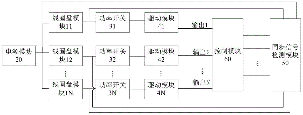
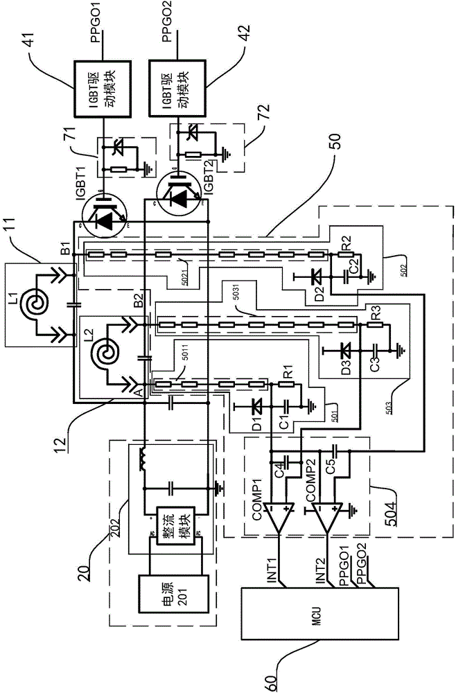
The invention discloses an electric cooker and a control circuit thereof. The control circuit of the electric cooker comprises N coil panel modules, a power module, N power switches, N driving modules, a synchronous signal detection module and a control module, wherein the power module is used for supplying power to the N coil panel modules; the power switches are connected with the coil panel modules in a one-to-one correspondence mode to form N resonance heating loops; the driving modules are connected with the power switches in a one-to-one correspondence mode so as to drive the power switches correspondingly; the synchronous signal detection module is used for detecting a synchronous signal of each resonance heating loop independently; the control module can control all the resonance heating loops to work independently at the same time or control each resonance heating loop to work independently according to the synchronous signals detected by the synchronous signal detection module. The control circuit can control all the resonance heating loops to work independently at the same time or control each resonance heating loop to work independently, so that the cooking requirement of users is fully met.

Description

technical field [0001] The invention relates to the technical field of electric heating appliances, in particular to a control circuit of an electric cooker and an electric cooker with the control circuit. Background technique [0002] In electric cookers such as rice cookers, induction cookers, electric pressure cookers and other products, multi-stage IH uses multiple independently working coil disks for heating control. Most of the current control schemes use series, parallel or scanning methods for heating. Usually, each section of coil cannot be controlled independently or the power of each section of coil cannot be adjusted independently, which cannot meet the cooking needs of users and brings inconvenience to users' lives. Contents of the invention [0003] The object of the present invention is to solve at least one of the above-mentioned technical drawbacks. [0004] Therefore, an object of the present invention is to provide a control circuit for an electric cook...

Claims


Application Information

Patent Timeline
IPC IPC(8): F24C7/08A47J27/00A47J36/00
Inventor 雷俊卞在银黄兵李新峰钟石刚董凯黄开平李信合张永亮黄庶锋何毅东徐双江王强袁宏斌
Owner FOSHAN SHUNDE MIDEA ELECTRICAL HEATING APPLIANCES MFG CO LTD
Learn More