Regulating valve and gas stove

A technology for regulating valves and valve bodies, which is applied in the field of cookers, can solve the problems of low gas supply pressure and cannot meet the needs of users, and achieve the effect of increasing gas concentration and improving practicability

Pending Publication Date: 2019-01-25
HANGZHOU ROBAM APPLIANCES CO LTD
View PDF7 Cites 4 Cited by
  • Summary
  • Abstract
  • Description
  • Claims
  • Application Information

AI Technical Summary

Problems solved by technology

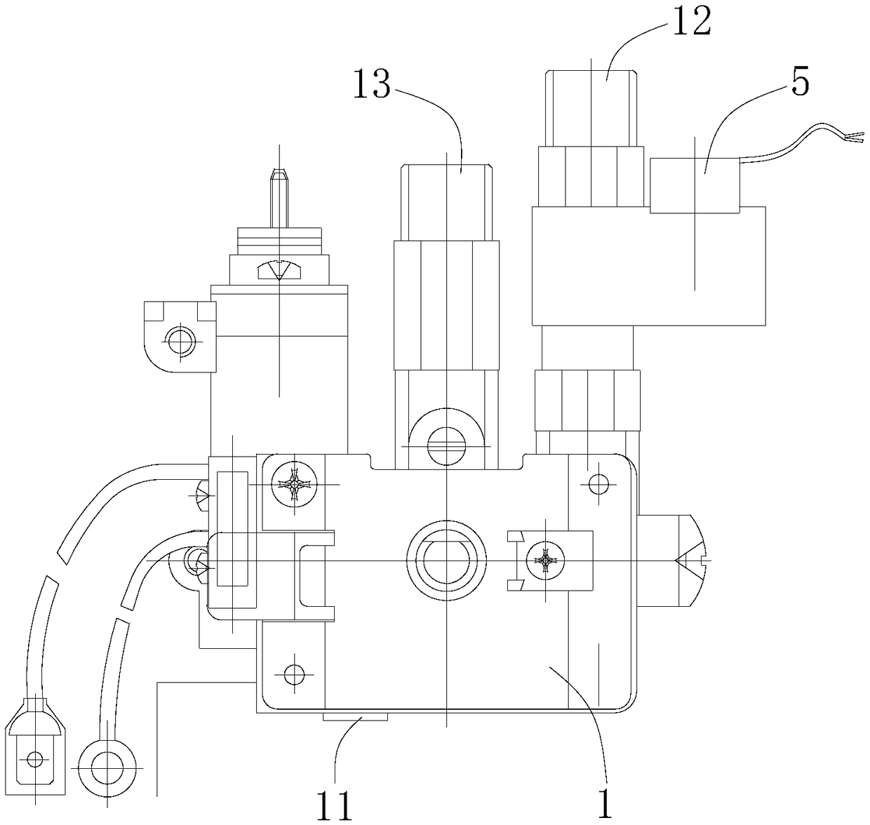
[0005] The purpose of the present invention is to provide a regulating valve and a gas cooker to solve the technical problem in the prior art that the gas supply pressure of the gas cooker is too small to meet the needs of users

Method used


Image

  • Regulating valve and gas stove
  • Regulating valve and gas stove

Examples


Embodiment Construction

[0025] The technical solutions of the present invention will be clearly and completely described below in conjunction with the accompanying drawings. Apparently, the described embodiments are some of the embodiments of the present invention, but not all of them. Based on the embodiments of the present invention, all other embodiments obtained by persons of ordinary skill in the art without making creative efforts belong to the protection scope of the present invention.

[0026] In the description of the present invention, it should be noted that the terms "center", "upper", "lower", "left", "right", "vertical", "horizontal", "inner", "outer" etc. The indicated orientation or positional relationship is based on the orientation or positional relationship shown in the drawings, and is only for the convenience of describing the present invention and simplifying the description, rather than indicating or implying that the referred device or element must have a specific orientation, ...


PUM


Abstract

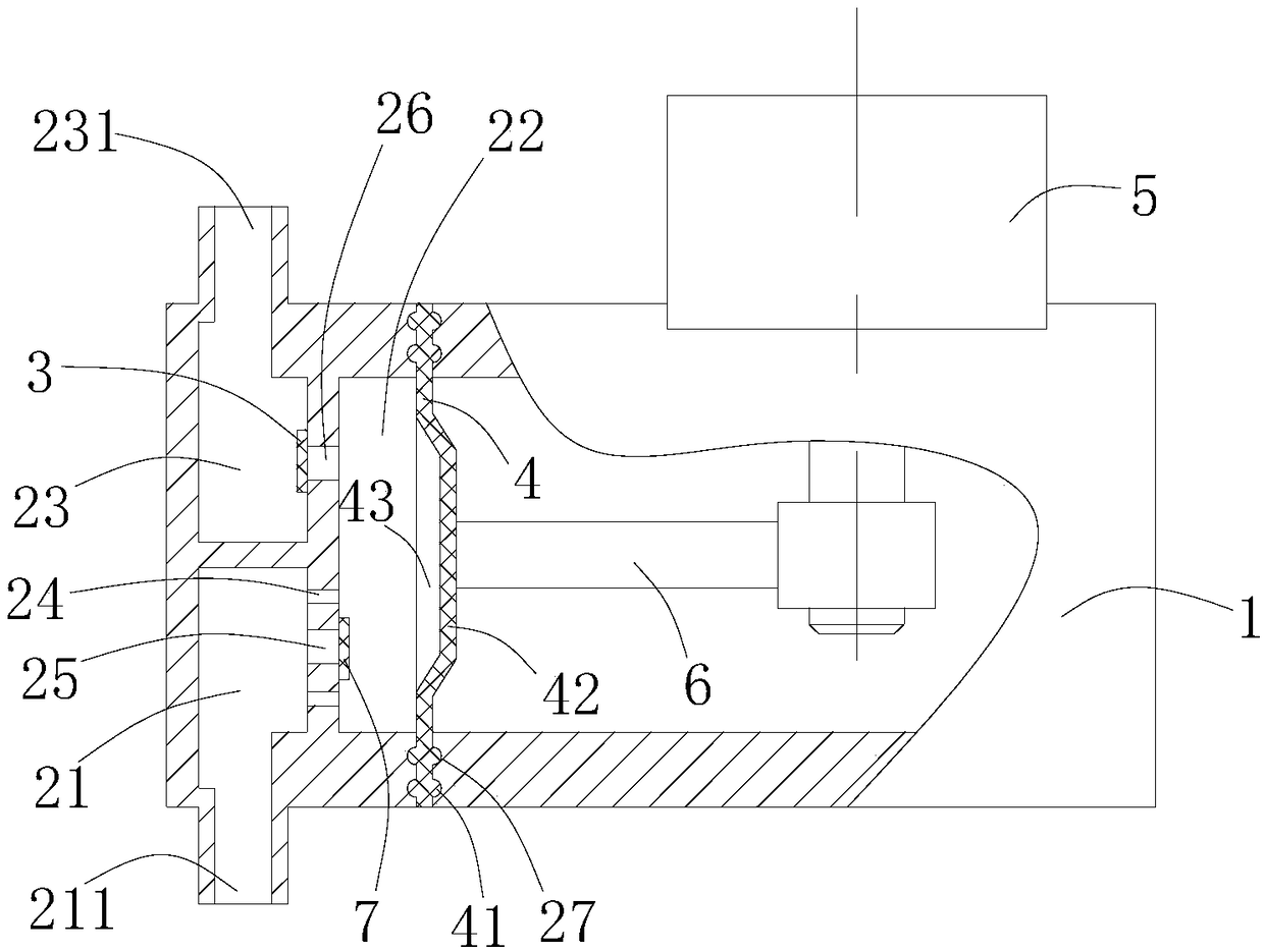
The invention provides a regulating valve and a gas stove, and relates to the technical field of cookers. The regulating valve comprises a valve body, wherein the valve body is provided with a first air inlet and a first air outlet which are in communication with each other, the valve body is internally provided with a pressurization flow passage and a pressurization mechanism, the pressurizationflow passage is communicated between the first air outlet and the first air inlet, and the pressurization mechanism can increase gas flow passing through the pressurization flow passage. The gas stoveincludes a burner and the regulating valve, and the first air outlet of the valve body of the regulating valve is in communication with a gas channel of the burner. The regulating valve can increasethe amount of external gas to the burner, the concentration of the gas at the position of the burner is improved correspondingly, and generated fire power is increased, thereby meeting users' requirements for normal completion of ignition of the burner at any time period and cooking fire power.

Description

technical field [0001] The invention relates to the technical field of stoves, in particular to a regulating valve and a gas stove. Background technique [0002] The gas stove is a kitchen appliance for heating and cooking food. When the gas stove is working, the gas enters the stove from the intake pipe, and after being adjusted by the regulating valve (the user adjusts it through the knob), it enters the burner, and at the same time, it is mixed with a part of the air. After mixing, the mixed gas enters the fire distributor, is ignited by the ignition device and ejected from the fire hole to form a flame, which is used to heat the pot placed on the pot support. [0003] Since the cooking time of home users is relatively concentrated, and the pressure of the gas supplied by the external gas supply department is constant, when multiple users use the gas stove for cooking at the same time, the gas supply pressure will be insufficient, the firepower of the gas stove will be in...

Claims


Application Information

Patent Timeline
Patent Type & Authority Applications(China)
IPC IPC(8): F16K17/18F16K31/04F24C3/12
CPCF16K17/18F16K31/04F24C3/12
Inventor 任富佳胡松方吕春明戴建红郁明跃
Owner HANGZHOU ROBAM APPLIANCES CO LTD
Why Eureka
Try Eureka