
Photovoltaic loop heating pipe assisted twin-heat-source heat-pump heat supply system

A dual heat source, volt loop technology, applied in heating systems, hot water central heating systems, heating fuels, etc., can solve the problem of the mismatch between the evaporator and the condenser, the disadvantage of the evaporator, and the effective use of solar energy and air energy at the same time. Operational performance impact and other issues, to achieve the effect of improving the area of ​​the collector is too large, solving the external power supply, and improving the comprehensive conversion efficiency

Inactive Publication Date: 2016-06-22
YANSHAN UNIV
View PDF5 Cites 2 Cited by
  • Summary
  • Abstract
  • Description
  • Claims
  • Application Information

AI Technical Summary

Problems solved by technology

[0002] The water temperature prepared by the solar photovoltaic photothermal heat collection system is generally lower than the outlet water temperature of the traditional solar hot water system. Coupled with the influence of weather factors, the hot water prepared by the solar photovoltaic photothermal heat collection system usually cannot meet the heating requirements of buildings. temperature requirements
The performance of the air source heat pump is greatly affected by the outdoor temperature, especially in cold and severe regions in winter, there will be frosting problems, which will cause the performance of the heat pump to decline or even fail to work normally
In the existing technology combining heat pipe, solar energy and heat pump, when the heat pump and heat pipe modes share the same condenser, the mismatch between the evaporator and the condenser is prone to occur due to the large difference in the working conditions of the two modes; and the existing evaporator The structural form of the device is not conducive to the effective use of solar energy and air energy at the same time

Method used


Image

  • Photovoltaic loop heating pipe assisted twin-heat-source heat-pump heat supply system

Examples


Embodiment Construction

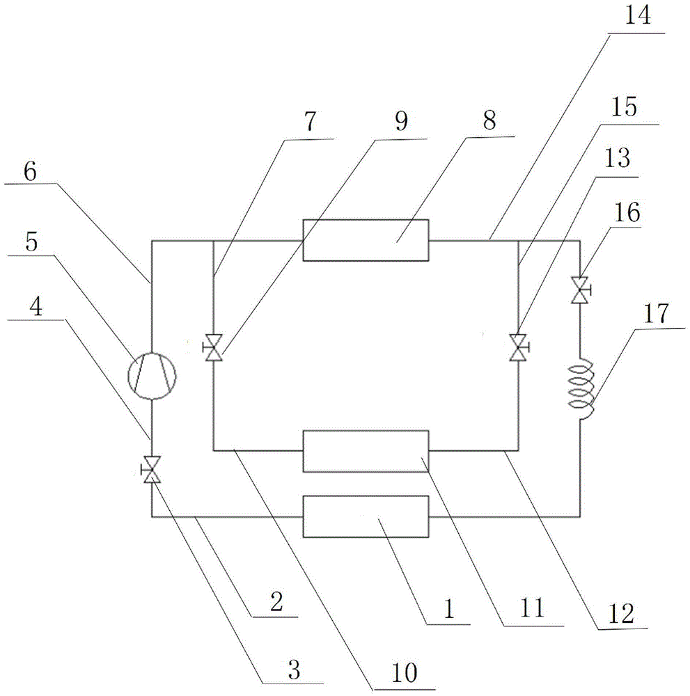
[0012] exist figure 1 In the schematic diagram of the present invention shown, the solar energy / air evaporator 1 is a spiral fin tube heat exchanger, one end of the solar energy / air evaporator is connected with an end of the pipeline A2, and the other end of the pipeline A is connected with the valve A3. One end is connected, the other end of valve A is connected with one end of pipeline B4, and the other end of pipeline B is connected with the air inlet of compressor 5. The gas outlet of the compressor is connected to the pipeline C6 and the pipeline D7 respectively, the gas outlet of the compressor is connected to one end of the condenser 8 through the pipeline C, and the gas outlet of the compressor is connected to one end of the valve C9 through the pipeline D. The other end of the valve C is connected to one end of the solar photovoltaic-loop heat pipe evaporator 11 through the pipeline E10, and the other end of the solar photovoltaic-loop heat pipe evaporator is connecte...


PUM


Abstract

Provided is a photovoltaic loop heating pipe assisted twin-heat-source heat-pump heat supply system. The photovoltaic loop heating pipe assisted twin-heat-source heat-pump heat supply system mainly comprises a solar / air evaporator, a pipeline A, a valve A, a pipeline B, a compressor, a pipeline C, a pipeline D, a condenser, a valve C, a pipeline E, a solar photovoltaic-loop heating pipe evaporator, a pipeline F, a valve D, a pipeline G, a pipeline H, a valve B and a capillary tube. According to the operation mode of a heat pump, solar energy and air are adopted as heat sources, the defect that an air source heat pump has low operation efficiency or can not operate in a low temperature environment is overcome, and the problem that the area of a heat collector in a common solar auxiliary heat-pump heat supply system is too large is solved; by arranging the evaporator in the loop heating pipe mode and the evaporator in the heat pump mode in a split mode, mismatch between the condenser and the evaporators when the two modes share the condenser is avoided; and the overall structure is simple, the solar photo-thermal utilization integrated conversion efficiency can be improved sufficiently, external power supply of the system is achieved, and the energy consumption of the heat supply system for buildings is approximately zero.

Description

technical field [0001] The invention belongs to the technical field of building energy saving, and relates to a heat supply system with a dual heat source heat pump. Background technique [0002] The water temperature prepared by the solar photovoltaic photothermal heat collection system is generally lower than the outlet water temperature of the traditional solar hot water system. Coupled with the influence of weather factors, the hot water prepared by the solar photovoltaic photothermal heat collection system usually cannot meet the heating requirements of buildings. temperature requirements. The operating performance of air source heat pumps is greatly affected by the outdoor temperature, especially in cold and severely cold regions in winter, there will be frosting problems, which will cause the performance of the heat pump to decline or even fail to work normally. In the existing technology combining heat pipe, solar energy and heat pump, when the heat pump and heat pi...

Claims


Application Information

Patent Timeline
IPC IPC(8): F24D3/18
CPCF24D3/18F24D2200/123F24D2200/14
Inventor 李洪付新书
Owner YANSHAN UNIV
Learn More