
Error measurement apparatus and measurement method for current transformer

A technology of current transformers and measuring devices, which is applied in the field of electrical measurement, can solve problems such as inconvenient use, difficulty in zero balance detection, and complex circuits, and achieves the effects of high automation, improved consistency, and improved measurement efficiency

Pending Publication Date: 2016-06-22
CHINA ELECTRIC POWER RES INST +2
View PDF0 Cites 20 Cited by
  • Summary
  • Abstract
  • Description
  • Claims
  • Application Information

AI Technical Summary

Problems solved by technology

The general transformer calibrator adopts the principle of differential balance comparison. The advantage of this kind of calibrator is its high accuracy, and its resolution can reach 1×10⁻⁸. It can be used to calibrate transformers of 0.0001 level and below. The disadvantage is that this kind of calibrator needs manual adjustment, it is difficult to check zero balance, and it is inconvenient to use
Although the working efficiency of the latter is higher than that of the traditional electrical calibrator, the circuit is complex and difficult to debug. When the differential signal is small, the measurement accuracy and stability are not good, and the repeatability is poor, and it is generally only suitable for testing 0.01 Transformers below the grade
[0005] The existing transformer calibrator can only be calibrated and traced at 50 / 60Hz. Due to the limitations of its components and working principle, none of them can work under the conditions of high harmonics or high DC components, and cannot be used to measure current transformers. The error characteristics of direct current and harmonic influence, so it is necessary to provide a new type of measurement device and measurement method

Method used


Image

  • Error measurement apparatus and measurement method for current transformer
  • Error measurement apparatus and measurement method for current transformer
  • Error measurement apparatus and measurement method for current transformer

Examples


Embodiment Construction

[0032] The present invention will be described in further detail below in conjunction with the accompanying drawings and specific embodiments.

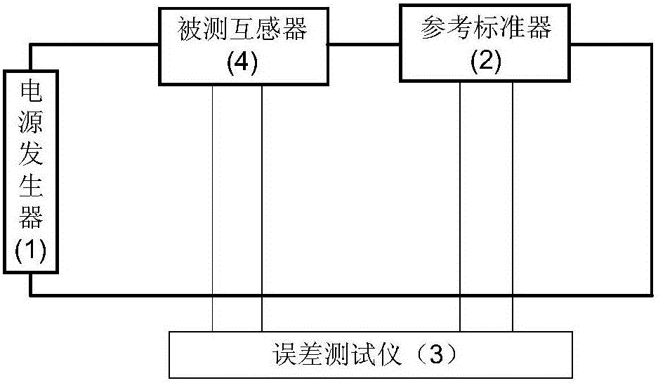
[0033] as attached figure 1 As shown, it is a structural block diagram of a current transformer error measuring device of the present invention, which is composed of a power generator 1, a reference standard device 2 and an error tester 3, and the power generator 1 is connected with the reference standard device 2 and the measured device respectively The transformer 4 is connected, the reference standard 2 is connected with the measured transformer 4 and connected with the error tester 3 respectively.

[0034] The power generator 1 can generate a high-current AC-DC composite signal or a half-sine wave signal, and apply the produced signal to the measured current transformer 4 and the reference standard 2;

[0035] The reference standard device 2 can accurately convert the AC and DC components in the measured large current signal into...


PUM


Abstract

The invention provides an error measurement apparatus and measurement method for a current transformer. The apparatus is composed of a power generator (1), a reference standard device (2) and an error tester (3). The power generator (1) generates a heavy alternating current-direct current synthesis signal or a sinusoidal half-wave signal and applies the generated signal to a tested current transformer (4) and the reference standard device (2); the reference standard device (2) can convert alternating-current and direct-current components in tested heavy current signals into small-current or small-voltage signals accurately, and the small-current or small-voltage signals are used as reference signals and are inputted into the error tester (3); and the error tester (3) carries out synchronous sampling, conversion, and calculation on a reference signal outputted by the reference standard device (2) and a tested signal outputted by the tested current transformer (4) to obtain a measurement result.

Description

technical field [0001] The invention relates to the field of electrical measurement, in particular to a current transformer error measuring device and a measuring method. Background technique [0002] Current transformer is the key equipment for electric power production, electric energy measurement and protection. In the process of power production, a large number of current transformers are used in power generation, power transformation and other links to measure and protect high-voltage and high-current electric energy. If there is a DC component in the primary current in the power grid, the iron core of the current transformer in the electric energy metering device will be magnetized, and the greater the magnetizing current, the greater the residual magnetism. In the case of no demagnetization, the residual magnetism can be kept until the next magnetization process. The influence of residual magnetism on the error of current transformer can be reflected in the magnetiz...

Claims


Application Information

Patent Timeline
IPC IPC(8): G01R31/00G01R35/02
CPCG01R31/00G01R35/02
Inventor 岳长喜雷民项琼王欢章述汉朱凯王雪
Owner CHINA ELECTRIC POWER RES INST
Learn More