Eureka AIR delivers breakthrough ideas for toughest innovation challenges, trusted by R&D personnel around the world.

Three-level inverter protection device and three-level inverter

A three-level inverter and protection device technology, applied in emergency protection circuit devices, output power conversion devices, electrical components, etc. Problems such as PWM drive interlock circuit of phase three-level inverter

Active Publication Date: 2016-06-22
深圳市英威腾光伏科技有限公司
View PDF6 Cites 12 Cited by
  • Summary
  • Abstract
  • Description
  • Claims
  • Application Information

AI Technical Summary

Problems solved by technology

The invention patent with the publication number CN102710116A discloses a PWM drive interlock circuit for two-level three-phase inverters. When DPPWMUT=1, DPPWMUB=1, and INVEN=1, the DSPOGATED resistor RVUHI=0, but the DSPOGATED resistor RVULO=1, the lower tube will still be turned on, and complete lockup cannot be achieved, and the DSP cannot know whether there is a logic error in the PWM drive signal, resulting in the inverter still working abnormally. Inverter PWM drive interlock circuit

Method used


Image

  • Three-level inverter protection device and three-level inverter
  • Three-level inverter protection device and three-level inverter
  • Three-level inverter protection device and three-level inverter

Examples


Embodiment 1

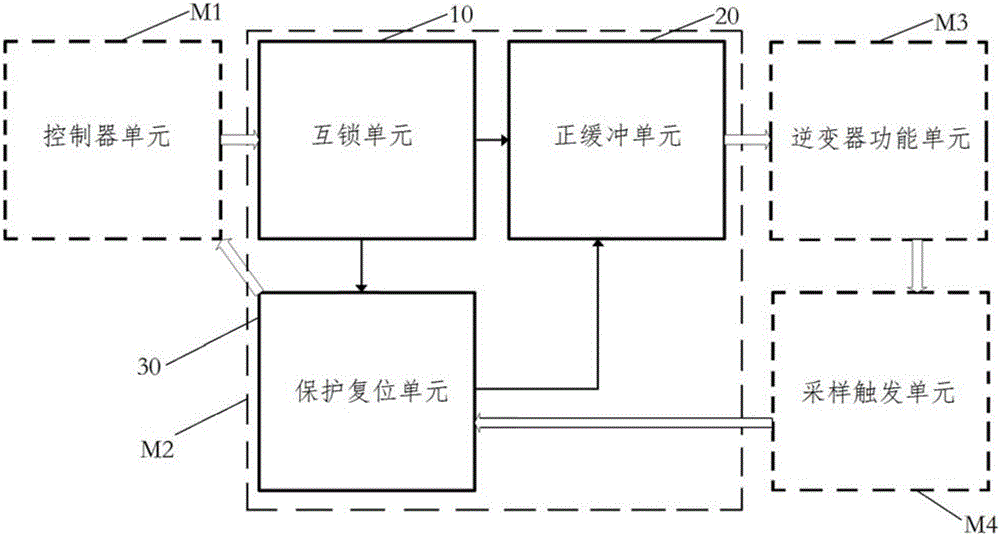
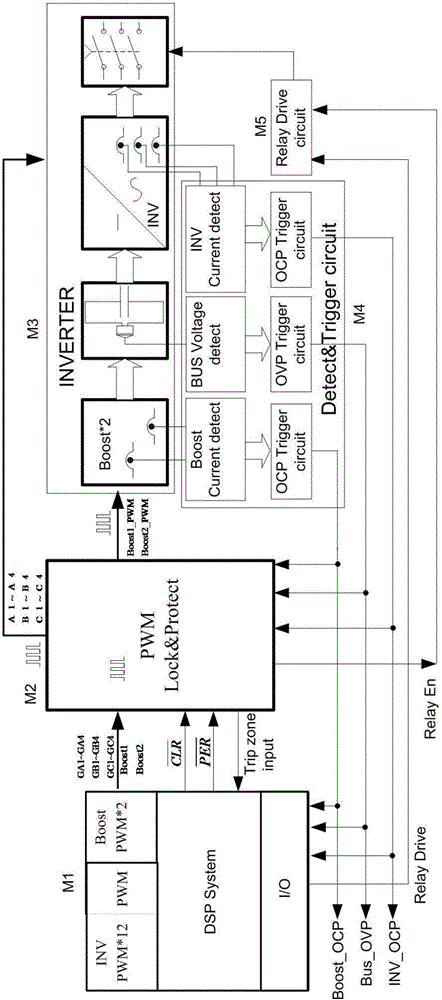
[0025] Such as figure 1 with figure 2 As shown, the three-level inverter of this embodiment includes a controller unit M1, a protection device M2, an inverter power unit M3, and a sampling trigger unit M4.

[0026] The controller unit M1 is connected to the protection device M2, the protection device M2 is connected to the inverter power unit M3, the sampling trigger unit M4 is connected to the inverter power unit M3, and the sampling trigger unit M4 outputs to the controller unit M1 and the protection device M2.

[0027] The controller unit M1 is used to provide a PWM driving signal for the protection device M2. The controller unit M1 has the function of generating PWM driving signals and I / O processing functions, and specifically may include a single or multiple control core units, such as DSP, FPGA or MCU with ARM architecture. Those skilled in the art can design the structure of the controller unit M1 according to the actual situation.

[0028] The protection device M2...


PUM


Abstract

The invention discloses a three-level inverter protection device and a three-level inverter. The three-level inverter protection device comprises an interlocking unit, a protection reset unit and a positive buffer unit. A switch interlocking module of the interlocking unit receives a PWM driving signal so as to output an interlock driving signal. A complementary logic module performs true-false logic computing on the PWM driving signal so as to generate a PWM complementary state signal. An error reporting signal module of the protection reset unit receives the PWM complementary state signal and a sampling trigger signal, when one of the signals is in an error reporting state, a judgment signal output by the error reporting signal module is an error reporting state, and an error reporting processing module blocks the positive buffer unit. In the driving interlock design aiming at I type and T type three-level photovoltaic inverters, the three-level inverter protection device and the three-level inverter can avoid accidents of damage to a power device because a driving signal is sent by mistake or a protection circuit does not act timely when the PWM complementary state signal or the sampling trigger signal is in the error reporting state.

Description

technical field [0001] The invention relates to the technical field of an inverter inverter control circuit and its logic protection circuit, in particular to a protection device for a three-level inverter and a three-level inverter. Background technique [0002] The application of three-level technology in the field of photovoltaic inverters is becoming more and more extensive. During the operation of photovoltaic inverters, there are usually various faults, among which the more serious faults are failures, and the main cause of failures is usually The bridge arm of the inverter unit of the photovoltaic inverter is directly connected. Most of this kind of through-through is caused by incorrect driving rules, abnormal driving, or program runaway due to unstable power supply of the control system. In addition, the serious delay of the protection circuit and untimely protection will also cause this kind of through-through. [0003] In the prior art, a circuit unit with an int...

Claims


Application Information

Patent Timeline
Patent Type & Authority Applications(China)
IPC IPC(8): H02H7/122H02M7/487
Inventor 凌家树
Owner 深圳市英威腾光伏科技有限公司
Why Eureka
Eureka Blog
Learn More